Leaderboard
Popular Content
Showing content with the highest reputation since 05/25/12 in all areas
-

Seismic Assessment And Retrofit Design - Masonry Infills and General
Howard Roark and 15 others reacted to Ayesha for a topic
I accidentally came across these useful case studies, which, I would like to share. You can use them if you are working on a commercial or residential building retrofitting project. These case studies provide insight about seismic retrofitting and also on analytical methods, that are used for building assessment. I would also like to give due credit to people who are involved in these studies. All these studies were performed under a US-Pakistani Joint Cooperation Project. The details for the project are. 6-Storey Mixed Use Building in Karachi.pdf 10-Storey Office Building in Karachi.pdf RS-4 Storey Academic Building in Karachi.pdf Five Storey Residential Apartment.docx16 points -
Building Drift in ETABS Drift is a very complex topic in structural engineering. It involves too many factors to arrive at a suitable decision. It involves engineering judgment, the phenomenon fresh engineers might not feel. In this article, I have tried to explain what is building drift, allowable limits, ways and means to check in ETABS models and to control the excessive drift. Please keep in mind, this article is not about the building drift as far as structural science is concerned, rather this topic of drift is related to ETABS software. First of all you must be familiar with the term story drift. For convenience, I am quoting here the definitions from UBC-97 code:- STORY DRIFT is the lateral displacement of one level relative to the level above or below. STORY DRIFT RATIO is the story drift divided by the story height. 1) Maximum Limits Now what for story drift limits? What is the maximum permissible value? Well it depends upon the type of drift. Is it seismic or wind? For seismic, I will refer to UBC-97 code which in section 1630.10.2 talks about drift limits for earthquake. Now in simple words, the maximum limit for seismic drift is:- delta M shall not exceed 0.025 x story ht (if building seismic period is less than 0.7) delta M shall not exceed 0.020 x story ht (if building seismic period is equal or greater than 0.7) Important to note here is that it talks about SEISMIC drift so SEISMIC building period not the WIND period. Now delta M = Max inelastic response displacement = 0.7R delta S where R = from Table 16-N delta S = displacement from static, elastic analysis this value is read from ETABS. you multiply this value by 0.7R to get delta M This was all about seismic drift, but for wind drift code is mute. I will refer you to ASCE 2005 commentary CC.1.2 So we can understand that the limit for wind drift is "on the order of l/600 to l/400" for "common usage". This is common thing, however, in reality this figure can be up or down depending upon the ductility of cladding material and finishes. However for common usage value of l/400 is thought to be well satisfactory. Here l means story ht. The concept of drift limits is same throughout all the governing codes, and the typical limits of story height by some number is same, but obviously you have to take care of the process of calculating the wind force or seismic forces. You should not calculate wind force from one code and apply limits of another code. 2) Load Combinations Once the drift limit has been determined separately for seismic and wind forces, now is the need to check the actual drift vs the limit. Determination of actual drift depends on the load combination and the period of recurrence. If not properly calculated, this may dramatically increase or decrease the accepted drift values in model. Seismic force E is always already factored so that's the reason its factor is always 1.0 in load combinations of ACI/ASCE code. The recurrence period for seismic force is 50 years. In seismic drift we do not convert it into service seismic force. Seismic drift is checked against the direct load case of EQx, EQy etc in ETABS. For wind drift, we need to convert 50 year wind to service wind force. It has been recommended by ASCE commentary CC.1.2 To convert 50 year service wind force to 10 year service wind force it is multiplied by 0.7, as the equation says, and other gravity loads; D and 0.5L are also added. So in a nutshell we create following load combinations in ETABS to check our drift:- DRIFTWx1 = D+0.5L+0.7Wx DRIFTWx2 = D+0.5L-0.7Wx DRIFTWy1 = D+0.5L+0.7Wy DRIFTWy2 = D+0.5L-0.7Wy For seismic drift, as discussed earlier, we do not need any combination, drift will be checked just on EQx and EQy load cases only. 3) How to check in ETABS Now we have obtained both the actual drift and the drift limit, but how can we do this in ETABS easily? Well, after creating the drift combinations as discussed in step 2, we need to do as below:- For seismic drift goto File>Print Tables>Summary Report Select the file name Scroll down to the end of the page, you will find out a section about drifts, similar to this one:- It displays the max drift for each lateral load case for each story. As we want the drift for wind to be on drift load combinations and not on wind load cases, so we will not compare this wind drift without limits. In this table we are going to check just the drift values of our ETABS model for individual seismic load cases; EQx and EQy. As you noticed, this table shows us values in fraction format. For example 1/105 that becomes 0.009523809524. This 1/105 value is story drift divided by story ht. It means delta S / story ht. Now this value is delta S. First we need to convert it to delta M by multiplying it with 0.7R. Assume R here is 3.5 so delta M = 0.7 x 3.5 x 1/105 = 7/300 = 0.023333 which is less than 0.025 so safe ( if T<0.7). So instead of calculating every time by 0.7R we can check these limits in other way. If our limit is 0.025 then the limit we get is 0.025/R/0.7. Assume R=3.5. Now the values in ETABS are inverse so our limit is 0.7x3.5/0.025 = 98. In ETABS the drift is reported as 1/x where x is some number. Now as long as x (some number) is greater than 98 our limit of 0.025 x story ht is being satisfied. This way you can quickly check and compare seismic drifts. Now for the wind drifts, goto Display>Show tables, select Point displacements>Story drifts and then select only drift combinations for results. Click on and then copy the table to EXCEL. To save time you can right click on EXCEL taskbar and select maximum and minimum. Then just select the column H or I and see the maximum value that should be less than H/400 to H600 limit (0.0025 t0 0.00167). Again the values reported in ETABS are divided by story ht. http://4.bp.blogspot.com/-9qv8XKHgL8Q/UALNKflmVsI/AAAAAAAAAEQ/AwKBYWt2iys/s320/image022-773193.jpg 4) Controlling Excessive Drift Values sometimes you may face problem of excessively large values in drift tables in ETABS. Well we are not going to talk about different measures and modeling techniques to control the drift values. We are going to talk about large numbers in drift tables. Sometimes it happens that a point or node is free in the model or is connected to a NULL line or very flexible section. Drift tables for example the story drift table in wind captures the maximum displaced points. Obviously the displacement of several meters in tables is not what we are looking for. Drift values (relative) may be still okay for these points, but it requires you to check the displacement values too before checking directly the drift. Unlock the model and remove all free points, check for any discontinuity and modify your models to remove all the errors.15 points
-

Welcome Everyone! :)
hali and 12 others reacted to UmarMakhzumi for a topic
Asalam-o-alikum wr wb everyone! I am very excited to announce the launch of "Structural Engineering Forum of Pakistan". Its a open discussion forum directed to Civil/Structural Engineers. The purpose is to have discussions, to shun ambiguity and to overall uplift the structural design practice. I welcome everyone aboard. I hope this forum meets serves its purpose, May Almighty ALLAH bless you all. Warm Regards, Makhzumi!13 points -
Torsion: Reinforced Concrete Members
Omer Ahmed and 10 others reacted to UmarMakhzumi for a topic
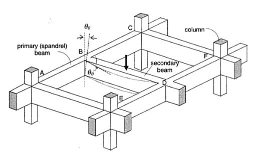
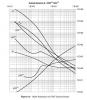
*SEFP Consistent Design* *Torsion: Reinforced Concrete Members * *Doc No: 10-00-CD-0001* *Date: May 24, 2013* Torsional forces, generally speaking, occur in combination with flexural and transverse shear forces. From a design perspective, we need to understand difference between two torsion types: Compatibility Torsion Equilibrium Torsion Compatibility Torsion Compatibility Torsion is when a member twists to maintain deformation compatibility; its induced in structural members by rotations (twists) applied at one or more points along the length of member. The twisting moments induced are directly dependent on the torsional stiffness of the member. These moments are generally statically indeterminate and their analysis necessarily involves (rotational) compatibility conditions(click on the image to enlarge). For the floor beam system shown above, the flexure of the secondary beam BD results in a rotation ǾB at the end B. As the primary (spandrel) beam ABC is monolithically connected with the secondary beam BD at the joint B, deformation compatibility at B implies an angle of twist, equal to ǾB at spandrel beam ABC, and a bending moment will develop at the end B of beam BD. The bending moment will be equal to, and will act in a direction opposite to the twisting moment, in order to satisfy static equilibrium. The magnitude of ǾB and the twisting/ bending moment at B depends on the torsional stiffness of the beam ABC and the flexural stiffness of beam BD. Now here is the fun part, the torsional stiffness of a reinforced concrete member is significantly reduced by torsional cracking. So, if you don’t design your spandrels for compatibility torsion, they will crack, increasing ǾB and reducing the induced twisting moment. To paint the same picture while using ETABS, set your torsional stiffness of the main beam to zero. This will also increase the amount of flexural reinforcement in your secondary beams. Moreover, considering design practice in Pakistan (since we never design beams without shear reinforcement), compatibility torsion can be ignored for regular structures, as minimum shear reinforcement in most cases would stand up to cracking torque. From ACI 318 commentary R11.6.1, Do note that there are some situations (such as circular beams supported on multiple columns) where both equilibrium torsion and compatibility torsion coexist. Also, eccentrically loaded beams, member curved in plan, and member of space frames will be subjected to torsion. See the attached “Timesaving-TorsionDesign-IA.pdf” as a go-by. Timesaving-TorsionDesign-IA.pdf Equilibrium Torsion In simplest words, Torsion is a limit state in this condition; a structure is subjected to equilibrium torsion when it can maintain equilibrium only by resisting the torsion. In such a case, torsional moment cannot be reduced by redistribution of internal forces since the torsional moment is required for the structure to be in equilibrium. From ACI- 318 (click on the image to enlarge). Moreover, see the structures below that defy gravity when subjected to different kind of loads by standing up to equilibrium torsion. Overall Building Torsion For overall building torsion, the torsional effects can be minimized by reducing the distance between the center of mass and center of rigidity. Center of Mass is the point where the mass of an entire story is assumed to be concentrated. The center of mass is crucial as the location of seismic force at a particular level depends upon it. The distance between the Center of Mass and the Center of Rigidity should be minimized, but may not be possible due to building geometry. Invariably, effects of torsion are present in at all buildings although analysis may show that in some buildings torsional effects are negligible.
 11 points
 -
Ubc Seismic Drift Limits
Omer Ahmed and 9 others reacted to UmarMakhzumi for a topic
*SEFP Consistent Design* *UBC Seismic Drift Limits* *Doc No: 10-00-CD-0003* *Date: June 04, 2013* The goal of this tutorial is to demonstrate how to evaluate building drifts and story drifts using UBC 97 guidelines. The philosophy behind Story Drift Limits is “Deflection Control”; In UBC 97, deflection control is specified in terms of the story drift as a limit on the lateral displacement of one level relative to the level below. The story drift is determined from the maximum inelastic response, ΔM. Let’s start by defining the design-level response displacements. The elastic deflections due to strength-level design seismic forces are called design-level response displacements. These are denoted by ΔS, where the subscript ‘s’ stands for strength design. Design level response displacements are what you get out of your software, when you run analysis. Please note that structural analysis softwares may provide these values in different formats; say a percentage of height or a direct output. Well, to calculate your story drifts, first you need to find maximum inelastic response displacements from your design-level response displacements. The maximum inelastic response displacement is defined as: ΔM = 0.7RΔS Where, R is the structural system coefficient, the subscript ‘m’ in ΔM signifies that we are calculating a maximum value for the deflection due to seismic response that includes inelastic behavior. Seismic drift values are much larger than wind values. UBC uses maximum inelastic response displacements rather than the design level displacements to verify the performance of the building. Seismic drift limits are 2% & 2.5% of the story height for long and short -period buildings. For a floor to floor height of 12 feet the max., allowable inelastic drift value would be 2% of 12 feet= 0.02*12*12 in=2.88 in. For wind for a 12 story height, drift would be L/400=12*12/400 =0.36 inches, A comparison of both wind and seismic drift limits shows that earthquake inelastic displacements are quiet large compared to wind displacements. That is why proper detailing is emphasized in seismic design. When calculating ΔS for seismic, make sure: You have included accidental torsion in your analysis. Use strength design load combinations: 1.2D + 1.0E + 0.5L & 0.9D + 1.0E. You are using cracked section properties for reinforced concrete buildings. Typical values are Icr walls= 0.5EcIg, Beams = 0.5EcI g & for Columns 0.5 - 0.7 EcIg. Use a reliability/ redundancy factor= 1 to calculate seismic forces. Whenever the dynamic analysis procedure of §1631 is used, story drift should be determined as the modal combination of the story drift for each mode. Determination of story drift from the difference of the combined mode displacements may produce erroneous results because maximum displacement at a given level may not occur simultaneously with those of the level above or below. Differences in the combined mode displacements can be less than the combined mode story drift. Example: A four-story special moment-resisting frame (SMRF) building has the following design level response displacements.(See attached Image) R= 7.0, I= 1 Time period= 0.6 sec (See the attached image for Story Information) Calculate: Maximum Inelastic response displacements. Story drift in story 3 due to ΔM. Check story 3 for story drift limit. Maximum Inelastic response displacements ΔM = 0.7RΔS ΔM = (0.7) (7) ΔS = (4.9) ΔS (See the attached image for Maximum Inelastic response displacements) Story drift in story 3 due to ΔM Story 3 is located between Levels 2 and 3. Thus ΔM drift = 5.39 - 3.43 = 1.96 in. Check story 3 for story drift limit. For structures with a fundamental period less than 0.7 seconds, §1630.10.2 requires that the ΔM story drift not exceed 0.025 times the story height. For story 3: Story drift using ΔM = 1.96 in. Story drift limit = 0.025 *(12*12) in = 3.6 in. > 1.96 in. Therefore, Okay.
 10 points
 -

STAMPING Structural DWGS; a crime or corruption
Muhammad Imran Zafar and 9 others reacted to Waqar Saleem for a topic
Dear Fellows I have encountered an issue; draftsmen/architects take projects from clients and make structural drawings without calculations and there are engineers whose stamps are available at printing shops which are stamped for very minimal charges. Structural engineers who are stamping as designer and as vetter are having filthy money without fulfilling their duties. These designers and vetters disregard the profession and engineering community, they do not have any ethics and sense of humanity. PEC do nothing or there is no complain against them. Being engineers and specially as structural engineers this is our responsibility to raise this issue to PEC or any other authorities and more to educate our engineering community that have respect and dignity in the profession, one must not disrespect his profession or let disrespected by such black sheep in the community. If a system/community have the ability to spit the wrong things out it remains alive and working perfectly. when system/community allows everything without check, such community is already dead. Structural engineers do not get projects who are working earnestly due to such people. Main aspect of design safety of humanity is at stack . This is totally against the PEC Code of Ethics. This is against the PEC Code of Conduct. Allah has bestowed us with great knowledge and brain to use for serving humanity and earning rizq e halal. We do use our brains rightly. We should stop this corruption by whatever means we can do.We must spit these non-professionals out of our community. This forum is one of the unique voice of structural engineering community, people comes here to get and share knowledge. I request to all the members that will stand with me on this issue. There is immense need to educate people that structural engineering is a business of life/economy saving, the fees structural engineers charge is nothing in comparison to the cost of lives lost during any incident due to incomplete and false designs or more accurate no designs. Regards10 points -
Pile Design
abbaskhan2294 and 8 others reacted to UmarMakhzumi for a topic
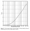
*SEFP Consistent Design**Pile Design**Doc No: 10-00-CD-0005**Date: Nov 21, 2017* This article is intended to cover design of piles using Ultimate Limit State (ULS) method. The use of ULS method is fairly new for geotechnical design (last decade). The method is being used in multiple countries now (Canada, Australia etc). The following items shall be discussed: Overview Geotechnical Design of Piles (Compression Loads, Tension Loads and Lateral Loads) Structural Design of Piles (Covering both Concrete and Steel) Connection of Pile with the foundation (Covering both Concrete and Steel) Pile Group Settlement Things to consider 1. Overview Piles provide a suitable load path to transfer super-structure loads to foundation where shallow foundation are not suitable - this can be due to a number of reasons like existing space constraints or suitable soil strata is not present immediately below structure. Other uses can be to meet design requirements like to have reduced settlement etc. This article shall cover the use of straight shaft cast-in-place concrete piles and straight shaft driven steel pipe piles. There are a number of additional piles types like belled concrete piles, precast concrete piles, screw / helical steel piles etc but the discussion to choose a suitable pile type is not in the intended scope of this article. The article is intended to discuss design requirements for straight shaft piles only (both concrete and steel) . The aforementioned topic about pile selection is a very diverse subject and requires a separate discussion on its own. Before I get into the nitty and gritty of pile design, it is important to highlight that as a structural engineer working on pile design, there are a number of parameters that you would require from the geotechnical engineer. Generally, these parameters are provided in the project geotechnical report. Based on those parameters, the geotechnical design of piles is performed first followed by structural design of pile. The next section talks about the geotechnical design of piles. 2. Geotechnical Design of Piles. Geotechnical design of pile means sizing of pile. This includes determining the following two geometric properties of piles: 1) Diameter or radius 2) Length Straight shaft piles embeded in soil derive their capacity from two sources. The first one is the skin friction along the pile length and the second one is the end bearing. In order to complete the geotechnical design of piles or in simple words to "size up the piles", you will need skin friction values for different soil strata through which the pile would penetrate or lie and the bearing capacity of the layer in which pile would terminate. This information is provided by the geotechnical engineer in the project geotechnical report. Generally, they would provide a table showing skin friction values of each soil layer for both tensile and compressive loads along with end bearing values of each layer. In addition to this, for areas susceptible to frost loading, the geotechnical engineer would also provide ad-freeze and frost heave forces. You can't design a pile without knowing what these values are. So this is something that you need from a geotechnical engineer. Once you have received the project geotechnical report with all the required information, you need to start sizing the piles. The easiest way to do it is to create an excel sheet and do preliminary calculations for different standard diameters like 200mm, 324 mm, 406mm, 460mm, 508mm, 610mm, 762mm and 914mm. The geotechnical report shall also provide recommendations if certain top soil layers need to be ignored or not. Example Problem: From your structural analysis, the maximum factored compressive load is 100 kN. and maximum factored tensile load is 50 kN. You need to size a pile (do geotechnical design) to meet that applied load. Sizing piles for geotechnical capacities is simple. Here is the formula for capacity of pile based on skin friction only (ignoring end bearing for simplicity): ULS Geotechnical Pile Axial Capacity: Pi * Pile Diameter * Total Embedment Length of Pile * Skin Friction Value * Resistance Factor Where, Pi= 3.14 Pile Diameter = 2* Radius Total Embedment Length of Pile = Pile Embedment Length - Frost Depth Skin Friction Values = See geotechnical for values Resistance Factor = 0.4 for compression and 0.3 for tension. For, the above problems, lets assume Skin Friction values of 80 kPa for both tension and compression and initial pile size (diameter) of 324 mm, Frost Depth of 3000 mm. For total length of 10m (lets assume a starting length), Total Embedment Length of Pile = 10m - 3m = 7m (Total Length - Frost Depth) ULS Geotechnical Pile Compressive Capacity= 3.14 * (0.324m) * 7m * 80 kPa * 0.4 = 228 kN > 100 kN Okay. ULS Geotechnical Pile Tensile Capacity = 3.14 * (0.324m) * 7m * 80 kPa * 0.3 = 171 kN > 50 kN Okay. The above problem shows you how to calculate the compressive and tensile capacities (also called the axial capacities) of the pile. For lateral capacity, you will need to know the modulus of sub grade information from the geotechnical engineer and use a software like LPILE to see the response against the lateral load. It is important to note that lateral deflection of pile is a service limit state meaning that it should be checked against unfactored loads. Generally, for petrochemical and oil and gas industries, pile service loads are defined as a deflection limit that will depend upon the maximum allowable movement of pile considering an elastic response from soil as well as the maximum movement piping and its attachments can take. Here is a scenario explaining that. For example, your geotechnical engineer recommends a maximum lateral movement of pile to be limited to 6mm so that soil around pile stays elastic. The structure you are designing, has a wind load deflection of 12mm. The pipes and equipment plus their connections shall be designed for 6mm+12mm = 18mm movement of structure. You need to notify piping of this deflection limit and if they are okay, you are good. If they are not, you will have to stiffen up the structure to lower the overall structure deflection and work with piping to see alternate routing for pipe. For pile design, you need to see what diameter pile shall have a capacity at 6mm lateral deflection greater than the applicable horizontal service load. To calculate pile capacity for different pile head movements, you will need to use LPILE or similar software. LPILE shall provide you a graph that would show you that how much a pile would move under applied lateral load or moment. LPILE is very easy to operate. You can look at the program tutorials and work your way through. It will also provide you the analysis results for a pile embeded in soil with soil modelled as springs along the length. This analysis result is important and allows us to see what is the maximum moment and shear developed in pile due to applicable load and based on combined response of soil and pile interaction. If you don't have LPILE, you can ask the geotechnical engineer, to provide you with pile lateral capacity graphs. In this case, you will need to provide the geotechnical engineer with estimated pile sizes, estimated axial and lateral loads, pile head condition (Fixed or Pinned) upfront. The goetech engineer will run the LPILE for you and provide you the graphs that will show the maximum load a pile can take against different lateral displacement values and would also provide the maximum moment due to max lateral load. I have done this on a number of projects and this is standard industry practice. 3. Structural Design of Piles. After completing the geotechnical design of pile, the structural design of pile needs to be performed. In order to do that, you will need to know the maximum moment in pile due to the application of axial and lateral loads. As mentioned above, the easiest way is to use LPILE output as it provides you with deformed shape of the pile along with the maximum moments and shears due to applied loads - the analysis of pile embedded in soil. Using LPILE analysis results, you can use beam-column capacity formulas to design a steel pile or column interaction diagram to design a concrete pile. Beam-Column capacity formulas vary with different codes so therefore I haven't included any example. For steel piles, corrosion allowance should be considered as per the code requirements. Generally its 1.5mm each exposed face so for pipe piles it will be 3mm considering exterior and interior face of the pile. 4. Connection of Pile with the foundation (Covering both Concrete and Steel) The connection of pile and foundation / pile cap is extremely simple for concrete piles. All you need to do is to develop the bars from concrete pile in concrete foundation/ pile cap. For steel piles, similar concept is there, except for you need to weld rebars on top of cap plate. 5. Pile Group Settlement Single pile or pile groups should always be check for settlement. Geotechnical consultant shall be contacted to get guidance on what method should be used. Methods like equivalent raft method or finite element analysis can be carried out to get settlement numbers. 6. Things to Consider For pile group, group effects are generally provided by the geotechnical engineer that can be applied to pile group. The group effects are a function of pile diameter and centre to centre spacing. Pile capacities are reduced if they are spaced closely. For straight shaft piles, rule of thumb is to place them greater or equal centre to center distance of to 3 * diameter of pile. For lateral loads, pile capacities are reduced at 3 * diameter spacing and generally piles need to be spaced at 5 * diameter to have no lateral reduction. Also, straight shaft piles if placed too close might result in pile installation issues. Some piles already installed might heave up if other piles are being installed in close proximity. Impact of pile driving to existing structures should also be considered especially if there is sensitive instrumentation installed in close proximity. Hope this article provides the much needed guidance on pile design. It is written for beginners and a lot of things have been kept simple. Your feedback is more than welcome. Please post any questions should you have. Thanks.9 points -
IITK Articles about Seismic Design
Howard Roark and 8 others reacted to UmarMakhzumi for a topic
I was browsing through my archives are noticed a bunch of articles written by NICEE (National Information Centre of Earthquake Engineering (NICEE) was established in IIT Kanpur with the mandate to empower all stakeholders in the building industry in seismic safety towards ensuring an earthquake resistant built environment. NICEE maintains and disseminates information resources on Earthquake Engineering. It undertakes community outreach activities aimed at mitigation of earthquake disasters. NICEE’s target audience includes professionals, academics and all others with an interest in and concern for seismic safety). The articles are free to publish as long as original content stays unchanged. These articles are good for fresh structural engineers and Civil/ Structural Engineering Students. The best thing about them is that they are only 2 pages and full of images. It literally takes less than 5 min to go through each. EQTip19.pdf EQTip20.pdf How architectural features effect buildings.pdf How buildings twist during earthquakes.pdf How do Beam-Column Joints in RC Buildings Resist Earthquakes.pdf How do Brick Masonry behave during Earthquake.pdf How do Columns in RC Buildings Resist Earthquakes.pdf How do Earthquake Affect Reinforced Concrete Buildings.pdf How Flexibility of Buildings affect their earthquake response.pdf How the ground shakes.pdf How to make building ductile for Good Seismic Performace.pdf How to make Stone Masonry Buildings Earthquake Resistant.pdf How to Reduce Earthquake Effects on Buildings.pdf What are magnitudes and intensity.pdf What are seismic effects on structures.pdf What causes earthquake.pdf What is seismic design philosophy of Buildings.pdf Why are Buildings with Shear Walls Preferred in Seismic Regions.pdf Why are horizontal bands necessary in masonry buildings.pdf Why are Open Ground Storey Buildings Vulnerable in Earthquakes.pdf Why are Short Columns more Damaged During Earthquake.pdf Why is vertical reinforcement required in masonry buildings.pdf Why should Masonry Buildings have simple Structural Configuration.pdf9 points -

Rectangular Concrete Tanks
Muneeb Badar and 8 others reacted to Badar (BAZ) for a topic
Guide for computing moments and shears in rectangular concrete tanks. rectangular concrete tanks.pdf9 points -
Diaphragm Flexibility
Suarez and 8 others reacted to Badar (BAZ) for a topic
*SEFP Consistent Design* *Diaphragm Flexibility* *Doc No: 10-00-CD-0004* *Date: August 07, 2014* I am writing this article about a very important, but mostly neglected topic of flexibility of diaphragm. I used to assume that all reinforced concrete slabs can be treated as rigid diaphragms. But as it turns out, only the slab with span-to-depth (depth is length of slab in direction of lateral loads) ratio of less than 3 and without horizontal irregularity can be treated as rigid diaphragm. The more important thing is that the span-to-depth ratio and horizontal irregularity is not the only criteria and one other factor also needs to be kept in mind before assigning rigid diaphragm to concrete slabs in numerical model of building. Another important concept that I learned, and it was a moment of epiphany for me, is about TRANSFER diaphragms. I had posted a topic “Amplification Of Forces In Etabs” earlier in this forum but we were not able to reach at a satisfactory conclusion. Now, I have the answer to that query: Back Stay effect. Another article is required to explain it , and this concept is not discussed in this article. This article is about flexibility of diaphragm. Diaphragms are horizontal members of the lateral-force resisting system of building structures. Their function is to distribute inertial forces, generated at its own level, as well as other levels, to vertical members of lateral-force resisting system. One kind of diaphragm only distributes inertial forces generated at its own level. This kind of behaviour is observed in buildings where there is a continuity of vertical members of lateral-force resisting system: building should not have a setback or podium at lower levels, or below grade levels. The other kind of diaphragm, known as “Transfer diaphragm”, not only distributes inertial forces generated at its own level, but also re-distributes forces coming from upper levels. This type of behaviour is typical of a building having setback or podium at lower levels, or below grade levels. Transfer slabs can attract huge forces due to a behaviour dubbed as BACKSTAY EFFECT. Now, coming to the issue of flexibility of diaphragm. According to ASCE 7-10, In addition to considering aspect ratio and horizontal irregularity as a basis for assuming concrete slab as a rigid diaphragm, the relative stiffness of adjoining vertical lateral load resisting system. Buildings with shear walls at ends and flexible frames in between are the ones where the assumption of rigid diaphragm leads to underestimation of drifts and erroneous distribution of base shear in vertical as well as horizontal direction (1)(2)(3); shear forces in middle frames can be reduced to 23% if rigid diaphragm is assigned in the model (1) for buildings with this type of structural configuration. M. Moeini et al. (2008) (3) conducted a parametric study using numerical analysis and proposed formulae that predicts the error associated with assuming concrete slab as rigid diaphragm. They also concluded that for buildings, without shear walls, rigid diaphragm assumption is suitable for irregular buildings as well. But, for long and narrow buildings with shear walls at ends, the assumption of rigid diaphragm is not suitable. The objective of writing this article was to warn engineers about the tendency of blindly assigning rigid diaphragm to concrete slab in any type of building configuration. The result could be underestimation of forces as well as drifts. Nakashima, M., Huang, T., Lu, L-W. “ Effect of Diaphragm Flexibility on Seismic Response of Building Structures”, In proceedings of 8th world conference on earthquake engineering. San Luis Obispo, MSc Thesis , “ An Investigation of influence of diaphragm flexibility on building design through comparison of forced vibration testing and computational analysis”, 2010. M. Moeini, B. Rafzey, W.P. Howsen, “Investigation into the floor diaphragm flexibility in rectangular reinforced concrete buildings and error formulae”, In proceedings of 14th world conference on earthquake engineering. The article is not finalized and would be completed in coming weeks.9 points -

Design For Shear And Torsion Using Etabs
Omer Ahmed and 8 others reacted to Syed Umair Haider for a topic
Dear Zain, I don't know the origin of document,you have uploaded for calculating torsional constant,but the methodology given therein is incorrect.As "Tcr" and "Tu" given therein are indeed threshold torsional strength and ultimate torsional stresses respectively, and are both design properties not analysis properties. (See ACI 318-11 section 11.5.1). Whereas the torsional constant, ETABS asks in "analysis property modification factors" is simply the torsional moment of inertia (J) used to determine torsional stiffness of a member (JG/L) i.e something else. As long as its value is concerned,then in building structures it is a general practice to use a negligible value like .001 to nullify beam's torsional stiffness.In this way, the torsional stresses (if arising due to compatibility of deformation i.e compatibility torsion ) are transferred via alternate load path (i.e redistribution of torsional moments occurred), considering that beam is unable to provide torsional restraint and in other condition if torsional stresses in beam is required to satisfy equilibrium of structure (where redistribution is not possible) then torsional stresses in beams remains independent of whatever value of "J" you have selected as equilibrium equations are necessarily satisfied independent of stiffness as "Compatibility is optional and equilibrium is essential". This approach of minimization of "J" economize beam sizes that arise from stringent combined shear and torsion requirement of building codes,but consequently beam sections designed in this way will start developing internal horizontal cracks (hairline cracks not affecting functionality of structure) due to torsional stresses and their torsional strength will continuously degrade till the design condition is achieved i.e negligible torsional strength of beam.But as the structure is designed to be stable without torsional stiffness of beam so it remain stable after this condition is achieved.However, the beam member itself cracks that doesn't affect the functionality of structure in any way. A very descriptive and clarifying description is available in "Reinforced concrete design by Arthur Nilson". As long as authentication of this approach is concerned then it is allowed by building codes as, 1, ACI-318-11 section 11.5.2.1 & 11.5.2.2. 2, UBC97 section 1911.6.2.1 & 1911.6.2.2 3, BS 8110-1 1997 section 3.4.5.13 Keeping in view above mentioned, it is a general practice to nullify torsional constant of beams in building structures and it is not required to use any iterative process to derive torsional constant of each beam section that is indeed not practical as there will be thousands of beam span in large structures.9 points -
Mentorship And Internship!!!
Engr Laique Zaman and 8 others reacted to Waqar Saleem for a topic
in engineering mentorship is very important for fresh engineers/final year students to get boost in learning basic techniques and practical knowledge from experienced seniors so is the internship for serious students.i request seniors that please show their willingness for mentorship and accommadte freshers/.final year students with them.that wud be great help for engineering students.please upload your willingness here and your field of experties and your location.thanx9 points -
Raft Modifier
Nawaz Qasim and 7 others reacted to UmarMakhzumi for a topic
I have worked with some engineers that like to assign high stiffness modifiers to rafts to get conservative flexural and shear design of foundation. Assigning modifiers would increase amount of rebar in your raft. I personally think that this is good practice as nothing is perfectly rigid and cracking in inevitable, which would result in loss of inertia and high flexural stresses. The general procedure is to create two models. One with no stiffness modifiers and one with modifiers for foundation/ raft. You should use the first model to calculate piles reactions and the second to do flexural and shear design. Thanks.8 points -
Beam/column Capacity
Nawaz Qasim and 7 others reacted to Badar (BAZ) for a topic
Ratio of flexural capacity of Beam/column is computed to preclude the formation of plastic hinges in columns for obvious reasons, refer to section 21.6.2 of ACI 318-11. Sum of flexural capacities of column at a joint should be 1.2 times the capacities of beam framing into the joint in particular direction. Etabs alerts user when the ratio exceeds; if it does not alert, it means either you are ok, or you have not activated corresponding seismic category (I think it calculates for category D E & F) for which this capacity needs to be computed. When capacity is exceeded, we can increase the size of column, or reduce the size of beam, or play with reinforcement of members. It has nothing to do with redistribution of moments; If both end of column will yield, during a seismic event, in a particular story, structure will most probably collapse. In a frame, that is resisting lateral loads, you cannot take away the ability of beam to develop negative moment; if you do not provide top reinforcement, it will not be called a moment resisting frame, and will not resist lateral loads..8 points -
Dynamic Analysis
Mazhar Amin and 7 others reacted to UmarMakhzumi for a topic
I have attached tutorials that will show you how to setup ETABS model for dynamic analysis. Go through all tutorials. There are lucid and self explanatory. OneDrive-2014-03-09.zip8 points -
Issues in ETABS results
Muhammad SAqib shah and 6 others reacted to Badar (BAZ) for a topic
I have observed few issues while getting the design results of reinforced concrete members from ETABS (v 9.7.4). I wanted to share this issues with you and get your input and observation on it. ETABS always considers the minimum eccentricity for selecting the design moment of columns irrespective of the probable behavior of the column, whether short or long column. See section 10.10.6.5 and its commentary of ACI 318-08 which deals with minimum eccentricity of long columns. You should always check the design moments that ETABS uses for columns if you want to bring down the cost of construction. If your model has lateral loads, ETABS will give you design moments in column irrespective of its status as braced or un-braced as per ACI 318 criteria. You should investigate if the storey under consideration is braced, or un-braced (10.10.5.2), and decide appropriate design moments of columns. ETABS has a tendency to select a time period of the building that is considerably less than the value obtained by the approximate method, Method A, of the section 1630.2.2 of UBC 97. To quote the FEMA 451 document: ''Because this formula is based on lower bound regression analysis of measured building response in California, it will generally result in periods that are lower (hence, more conservative for use in predicting base shear) than those computed from a more rigorous mathematical model". So, there is no need to use the value of time period that is lot less than Ta. One should always check the time period used by the software; ETABS can overestimate the seismic force by more than 2 times. Method A gives lower T and higher V, so FEMA 451 has advised not to use the value of time period less than this value even if rigorous analysis gives a lower value. I have seen the results where Etabs have use the value of time period less than Ta; in-fact as low as 0.5Ta, which can increase the base shear two times.7 points -
Sefp Consistent Design
Waqas Haider and 6 others reacted to UmarMakhzumi for a topic
Salaam All, Looking forward to develop a series of articles under the title of "SEFP Consistent Design". The aim is to provide simple and lucid examples for our Pakistani Engineers that use UBC 97; examples will serve as quick reference and try to clarify misconceptions prevalent in design offices. Anyone, who would like to volunteer on this is most welcome. As the name indicates, "consistent design" is meant to spread common understanding of complex code clauses that a design engineer faces on a day to day basis. e.g., calculating story stiffness, or designing a flexible diaphragm. Examples would be pure, and written by authors with copyrights to SEFP. Current target is to have at least 2 examples published per month. I hope this will help young engineering to develop a rock-solid understanding and design the right thing rather than saying yes to whatever they are told to follow.That's my goal. Any ideas, input, volunteering in appreciated. Thanks.7 points -
Site Guidelines and Forum Posting Rules
Imam Hoshen and 6 others reacted to UmarMakhzumi for a topic
Salam Everyone! We are a steadily growing community now. I thought about posting forum rules which are always a good idea to keep new members streamlined to forum decorum. Please do share your thoughts on any modifications to the rules. Read the forums rules and guidelines before posting for the first time. Please use first names to address people & don't address anyone with a prefix. Calling someone Sir is prohibited. Search the other posts to see if your topic is already covered. Use a meaningful title for your thread and topic tag. Do not use a forum to promote your product, service or business. Be civil. Personal differences should be handled through email or IM and not through posts displayed to everyone. Stay on topic. Ignore spammers, respond to them personally and not through the board, or report them. Use plain text over HTML if you want your post to be readable by everyone. In order to be understood by most people, use correct spelling, grammar and avoid slang unless you know the word or phrase will be understood by other members. Do not double post (post the same message twice in one thread) or cross post (place the same message across several forums). Act in a give and take manner; help others as often as or more than you ask for help. Do not use all caps or SHOUT in your posts. In addition, one exclamation point is enough. When replying to a post, do not quote more from the previous post than you have to. Do not post new problems on someone else's thread and interrupt a topic of discussion. Do not use someone else’s thread for a private conversation. SEFP prohibits warez, cracks or illegal downloading of software and similar topics. Watch your sense of humor, posts may be read by people from a variety of backgrounds and ages. Do not use a huge and annoying signature, a modest signature is fine, moderators may remove large ones anyway. Do not post any information that you want private. Posts should not contain personal, identifiable information or content embarrassing to others. Do not post content that violates a copyright. Do not post ”empty” or useless responses, such as just ”lol” or ”cool.” Only post responses when you have something to contribute. Write concisely and do not ramble. Do not use words like ”urgent” or ”important” in your subject line, be patient. Post stuff on the forum rather than sharing through other means(email etc). If your desired attachment type is not supported, inform the moderators so that changes to board can be made. You can always zip files and upload them. Do not chastise newbies.7 points -
Building Drifts In Etabs
JL07 and 6 others reacted to UmarMakhzumi for a topic
Good article; I will throw my two cents. Seismic drift values are much larger than wind values. UBC uses maximum inelastic response displacements rather than the design level displacements to verify the performance of the building. As stated above, the seismic drift limits are 2% & 2.5% of the story height for long and short -period buildings. So, for a floor to floor height of 12 feet the max. allowable inelastic drift value would be 2% of 12 feet= 0.02*12*12inches=2.88 inches. For wind for a 12 story height, drift would be L/400=12*12/400 =0.36 inches, A comparison of both wind and seismic drift limits shows that earthquake inelastic displacements are quiet large compared to wind displacements. That is why proper detailing is emphasied in seismic design. Moreover, when calculating ΔS for seismic, make sure: you have included accidental torsion in your analysis. use strength design load combinations: 1.2D + 1.0E + 0.5L & 0.9D + 1.0E You are using cracked section properties for reinforced concrete buildings. Typical values are Icr walls= 0.5EcIg, Beams = 0.5EcI g & for Columns 0.5 - 0.7 EcIg.7 points -
Diaphragm
Shahzad Khan and 6 others reacted to UmarMakhzumi for a topic
Diaphragms connect all individual members into a seismic force resisting system. If you have concrete floors, it is imperative that your floor will do the above mentioned job plus distribute the seismic load to all the connecting members too. Diaphragms can be rigid or flexible depending upon their stiffness. For practise in Pakistan, if your flooring is type conc slab > 5" consider your diaphragm to be rigid. A rigid diaphragm distributes forces to connecting members based on connecting members stiffness, where as a flexible diaphragm distributes loading based on tributary areas of supporting members to diaphragm. Take diaphragm as a frame that connects all members, and makes them act together.7 points -
Long Term Deflection Multiplier
asadishaq and 6 others reacted to Badar (BAZ) for a topic
long term deflection multiplier accounts for deflection in members due to shrinkage and creep behavior in an approximate way. It is approximate because instantaneous dead deflection is multiplied by deflection multiplier and then this value is added in DL and LL deflection to get long-term deflection. Self weight multiplier option is used the software to compute dead weight of structure.If it is 1 then dead dead weight will be multiplied by 1. I edited title of thread as it can help in searching for particular topic in forum,I hope you will not mind.7 points -

Safe Iterative Uplift Analysis
Nawaz Qasim and 6 others reacted to WR1 for a topic
The main difference between SAFE 8 and 12 is that SAFE 8: was analysis 2D plate behaviour only SAFE12: by default it takes full analysis rather than 2D plate I dont my self aware of the full analysis which SAFE 12 does but the answer to the question that why NON LINEAR UPLIFT analysis in SAFE 8 takes no time and why in 12 it takes hours. We faced this problem and asked CSI guyz! because personally i dont like the SAFE 8 interface but there were people saying that if you have to do the non linear analysis export it to SAFE 12 which i really dont like. SAFE 8 was doing only 2D plate analysis (so you dont have to put restraint in x and y) only vertical springs. But in SAFE 12 if you run the analysis and check the log you will find that there is instability error because of no restraint in x and y. in SAFE 12 the options to select non linear uplift analysis are also very complex. Its not clear to select NON LINEAR UPLIFT in individual load cases or to select the option CONVERT COMBO TO NON LINEAR COMBOS well dont select the first option to check UPLIFT in each load case (results will be very strange) rather convert all load combos to non linear for uplift (results will be fine) but remember here that if you are doing 3d analysis without restraining in x and y your simplest model could take upto 3 hrs to run bcz of instabilities. to compare the results with SAFE 8 and to save run time goto RUN>Advanced options> and select 2d plate analysis option so by selecting just option you convert safe 12 to 8. no need to use the older version of SAFE and also note that in SAFE 12: Tension is + and Compression is - SAFE 8: Tension is - and Compression is +7 points -
Tallest Building In Pakistan
haro0n and 6 others reacted to UmarMakhzumi for a topic
This building promises to be tallest in Pakistan when completed. Project Description: Bahria Town Icon consists of two towers which are identical up to 8 floors i.e. 7 basements for car parking and 1 ground floor. Tower-1 comprises of 70 levels for office space and Tower-2 comprises of 30 floors for residential purpose. Client: AAA Partnership (Pvt.) Ltd. - Karachi. Location: Karachi. Architect: Arshad Shahid Abdullah (Pvt.) Ltd. - Karachi. Engineer: ESS-I-AAR - Karachi. (Structural) Beg Associates - Karachi. (Structural) WSP - UAE. (Structural) CFA: 2,230,500 m2; (24,000,000 ft2) Estimated Cost: USD 162.5 Million (PKR 13 Billion) START DATE April, 2010.7 points -
ETABS: Thin Shell Vs Membrane
Waqar Saleem and 5 others reacted to Badar (BAZ) for a topic
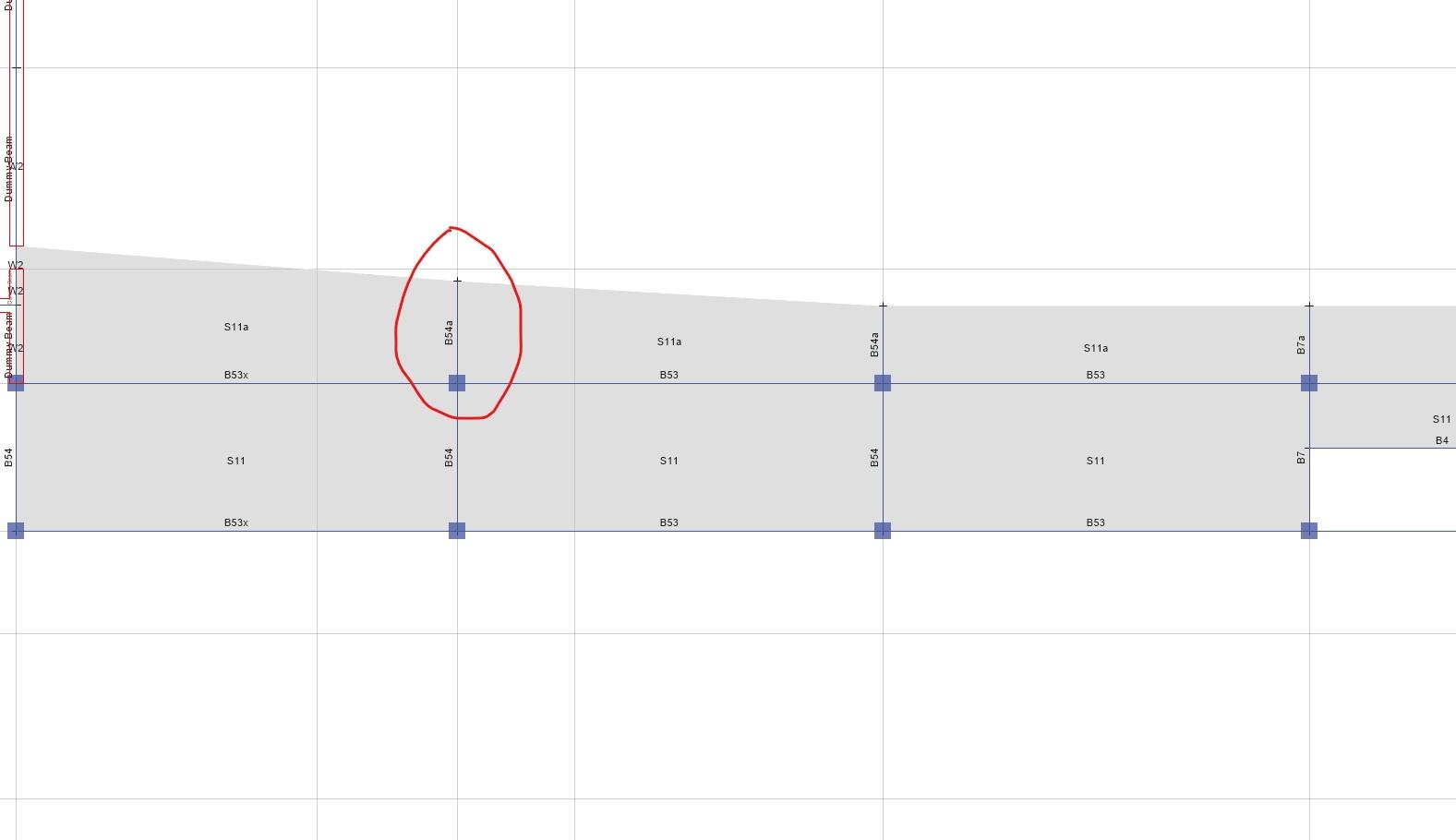
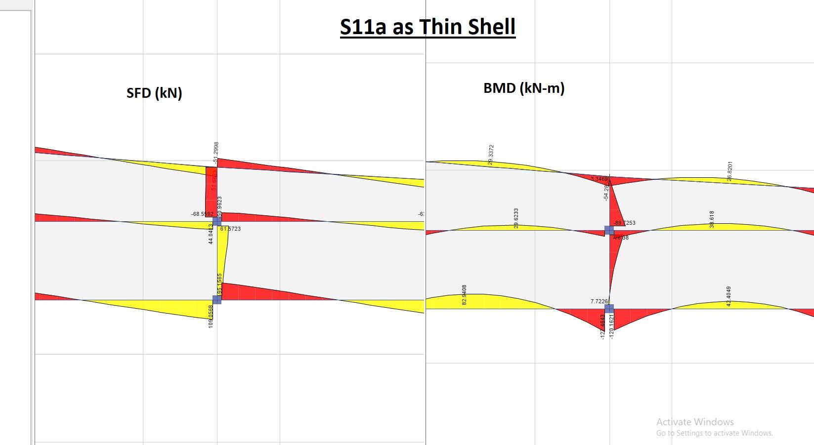
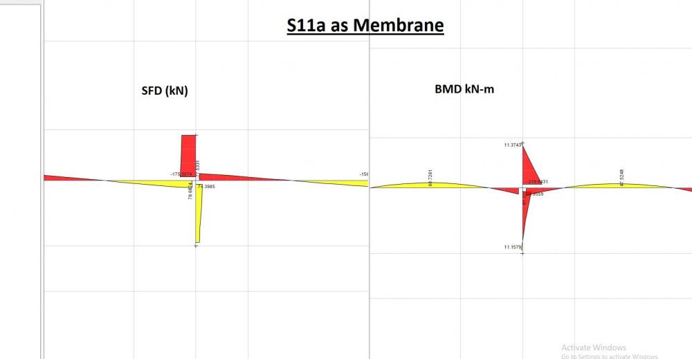
Young engineers often ask about whether to select membrane or thin shell or thick shell for modelling area elements such as RCC slab. I am going to talk about the difference in the results when choosing thin-shell or membrane. This is what makers of ETABS says about the topic. I will quote the following to clear out the structural difference between the two: "Load which is applied to membrane objects transfers directly to supporting structural objects, whereas meshed shell objects have bending stiffness and therefore resist a portion of the load through flexural deformation. As a result, less load will be available to transfer to beams located under a shell, while 100% of the load will transfer through a membrane". Lets see how much can the results differ. Figure below shows the partial framing plan of a level in the building I will discuss how the modelling of S11a as thin-shell or membrane will effect the design shear and moment on the beam B54a, see figure above. The figure below shows the design forces obtained against the gravity loads for the membrane case: The figure below shows the design forces obtained against the gravity loads for the thin-shell case: Based on the results presented above, B54a's design shear increased by 155%, and its design moment by 147% as compared to S11a's behavior as membrane. Now the question, that a Structural engineer needs to ask is: Which result is more appropriate or which result captures the actual behavior more realistically? And that is where you engineering judgement comes into play.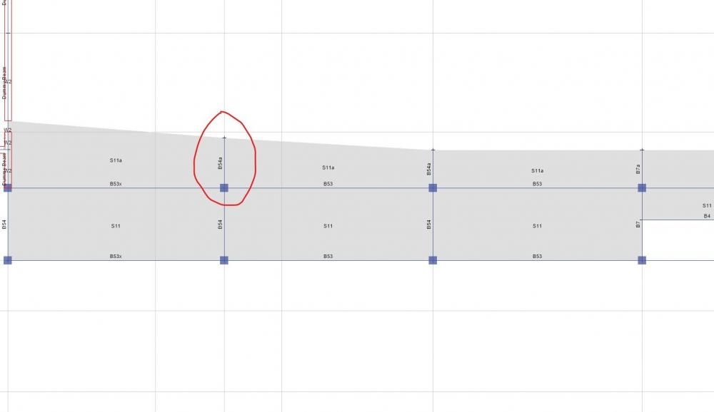
 6 points
 -

Rules of Thumb for Providing Reinforcement in Joints
Ayesha and 5 others reacted to Simple Structures for a topic
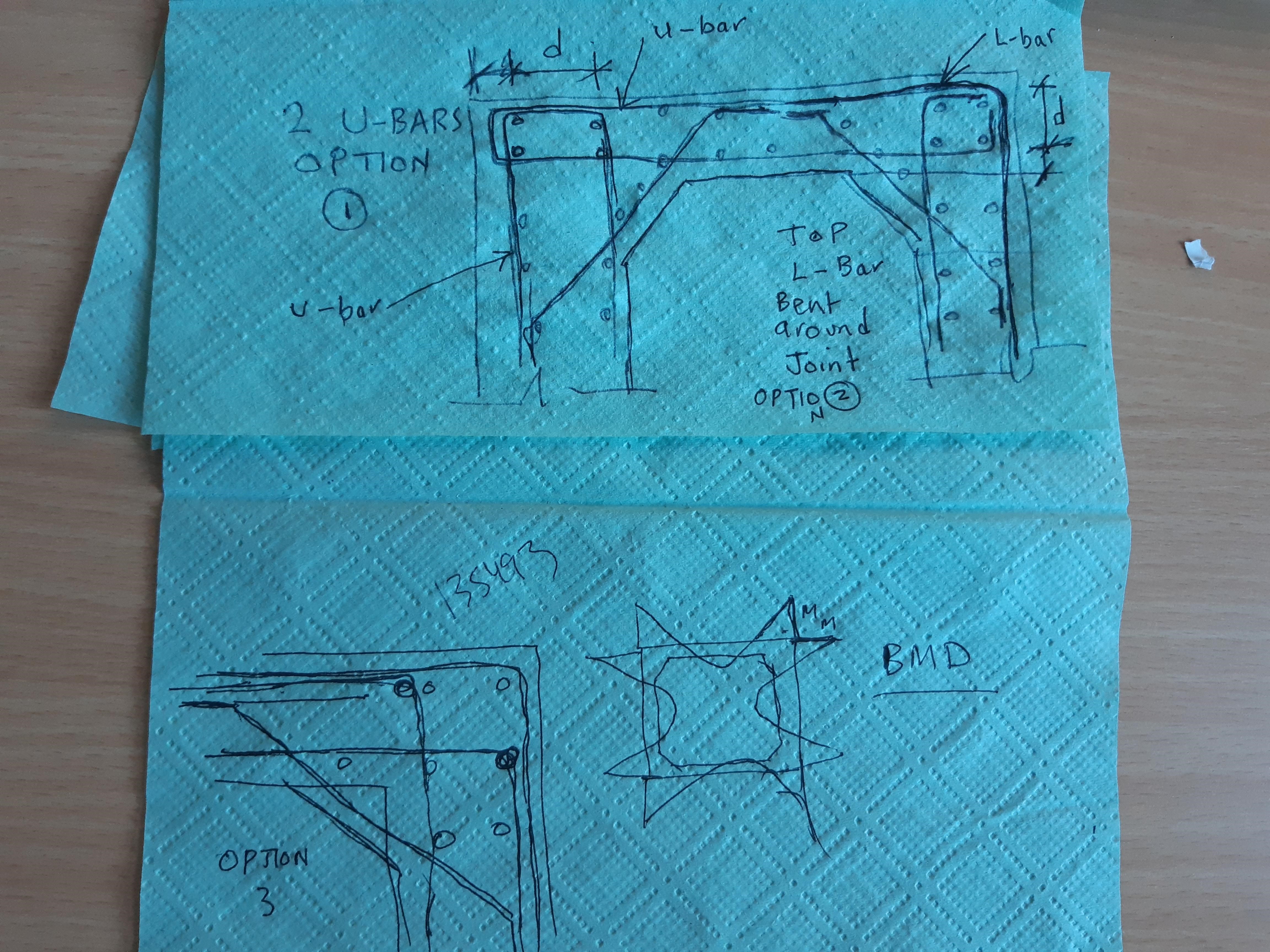
Culverts - first determine bending moment (tensile surfaces) and reinforce either one of two ways: See hand sketch below - once you know moment and effective depth of tension reinforcement you can design the joint. 1. U-bars coming in from slab and wall and connecting in corner. 2. or, Top/outer bar bent around the joint. 3. Option 3 is to use L-bars at joint, - see sketch below for all three ways you can detail a culvert corner - your engineering judgement is determine which detail best suits your design! Spacing of reinforcement tend to be closer to limit serviceability stress and hence crack width in concrete to <2mm - for reinforcement durability, and to stop water corroding the reinforcement, and to have a watertight structure; Movement joints are tricky in culverts. Make sure the concrete (or cement) selected is ok for, (i) against corrosive soils and (ii) chemicals in (waste) water.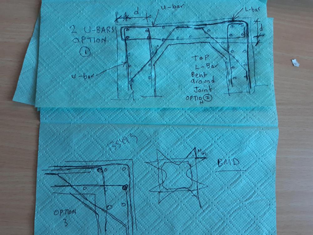 6 points
 -

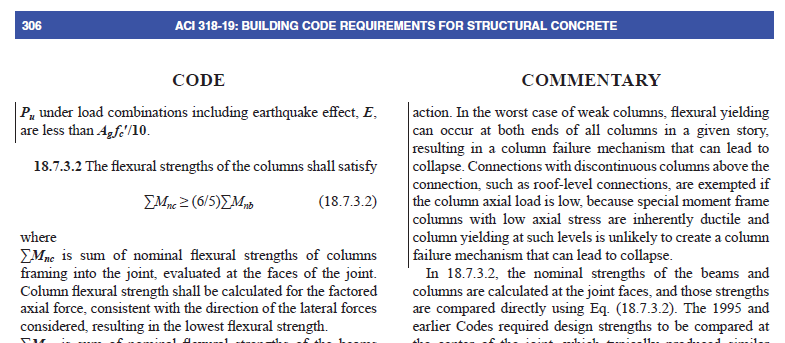
6/5 beam to column capacity check in the last floor
SAAD.KHAN. and 5 others reacted to Ali Karami for a topic
btw, i found this in ACI318-19: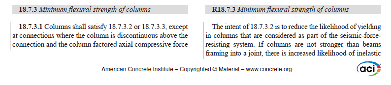
 6 points
 -

Slenderness of Columns
abbaskhan2294 and 5 others reacted to EngrJunaid for a topic
The quick method to check weather the design of slender column is fine or need to increase the column size are as follows; 1- In order to get the moments along column height accurately, divide the column into 2 or 3 segments. 2- Apply modifier. 3- Activate the P-Delta option from define menu. 4- Run the analysis and design with P-Delta and check the Non sway magnification factor i.e. delta(ns) in design summary of the column (see the pic attached). This delta(ns) must be less than 1.4. If this exceeds the limit of 1.4, increase the column size otherwise the column design is OK. Correction by seniors in my above steps will be highly appreciated.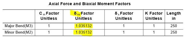 6 points
 -

IS PAKISTAN PREPARED ENOUGH TO HANDLE THE NEXT "BIG ONE"??
Badar (BAZ) and 5 others reacted to Fawad Najam for a topic
IS PAKISTAN PREPARED ENOUGH TO HANDLE THE NEXT "BIG ONE"?? https://www.express.pk/story/968021/ Errata: The magnitude of 2005 Kashmir earthquake is mistakenly typed as 8.6. Actually it was a M7.6 event.6 points -

Construction/Cold joint location in RC Column/walls
abbaskhan2294 and 5 others reacted to EngrUzair for a topic
Here are my two cents:- 1. General guidance regarding placement of construction joints in RC work has been provided in Section 6.4 of ACI 318-08 and its commentary. Some clarity is given in section 6.4.3, where it is stated that "Construction joints shall be so made and located as not to impair the strength of the structure. Provision shall be made for transfer of shear and other forces through construction joints." For transfer of shear etc through construction joints, reference is made to the ACI Section 11.6.9 that deals with the calculation of shear-friction, at the interface between two concretes cast at different times (beside other situations described in section 11.6.1 of the code). Moreover, Section 6.4.4 suggests that "Construction joints in floors shall be located within the middle third of spans of slabs, beams, and girders. 2. Regarding construction joints in columns, however, Section 6.4 does not provide guidance clearer than that in Section 6.4.6 stating that the "Beams, girders, or slabs supported by columns or walls shall not be cast or erected until concrete in the vertical support members is no longer plastic." And, the commentary section R6.4.6 explains that "Delay in placing concrete in members supported by columns and walls is necessary to prevent cracking at the interface of the slab and supporting member caused by bleeding and settlement of plastic concrete in the supporting member." 3. The support member (referred in previous paragraph) will generally be a column or a wall. And, in a simplified form, Section 6.4.4 & its commentary are advising us NOT to cast beams & slab monolithically with the wall or column, BUT only after the supporting column (or wall) concrete has hardened, in order to avoid plastic cracking at the beam-column (or beam-wall) joint. 4. In our normal field practice (within Pakistan as well as abroad), beams & slabs are cast at least one day after casting of columns or supporting walls. This gap of one day (between casting of column & beam concretes) ensures that the column (or wall) concrete poured one day earlier has hardened (is no longer plastic), thereby avoiding any possibility of plastic cracking (discussed in paragraph 2 above). 5. Now coming to your queries; In general terms, it is preferable to cast the column in one pour.. However, in compelling circumstances it may be done in more than one pour too, subject to certain conditions. Already described in initial paragraphs. This is the normal & IMHO desirable practice, according to ACI code Section 6.4.6. IMO, leaving 9" or 12" column depth below the beam soffit is excessive & undesirable. It should not be more than 1" or 2" in any case. IMO, this practice is based on the requirements of ACI 318-08 (also ACI 318-11) Section 6.4.6. The same requirement is available in ACI 318-14 Section 26.5.7.2 (a) as well. HTH Regards.6 points -
Comments/Observations regarding modelling in ETABS
tanvirce12 and 5 others reacted to Badar (BAZ) for a topic
*Comments/Observations regarding modelling in ETABS* *Doc No: 10-00-CD-0006* *Date: May 06, 2017* Some of the observations made during extraction of results from ETABS (v 9.7.4), for design of reinforced concrete members, are being share in this article., 1) Minimum Eccentricity ETABS always considers the minimum eccentricity for selecting the design moment of columns irrespective of the probable behavior of the column, whether short or long column. See section 10.10.6.5 and its commentary of ACI 318-08 which deals with minimum eccentricity of long columns. You should always check the design moments that ETABS uses for columns if you want to bring down the cost of construction. 2) Unbraced/ Braced Preference If your model has lateral loads, ETABS will give you design moments in column irrespective of its status as braced or un-braced as per ACI 318 criteria. You should investigate if the storey under consideration is braced, or un-braced (10.10.5.2), and decide appropriate design moments of columns. 3) Time Period ETABS has a tendency to select a time period of the building that is considerably less than the value obtained by the approximate method, Method A, of the section 1630.2.2 of UBC 97. To quote the FEMA 451 document: ''Because this formula is based on lower bound regression analysis of measured building response in California, it will generally result in periods that are lower (hence, more conservative for use in predicting base shear) than those computed from a more rigorous mathematical model". So, there is no need to use the value of time period that is lot less than Ta. One should always check the time period used by the software; ETABS can overestimate the seismic force by more than 2 times. Method A gives lower T and higher V, so FEMA 451 has advised not to use the value of time period less than this value even if rigorous analysis gives a lower value. I have seen the results where Etabs have use the value of time period less than Ta; in-fact as low as 0.5Ta, which can increase the base shear two times. (For a complete discussion on time period, please see the following this thread that complements this section). 4) Stiffness Modifiers First thing is related to modelling the bending stiffness of flexural members, for strength level loads, that is representative of their condition near failure. The ACI code specifies the modifier of 0.35 on gross moment of inertia to represent its condition at yielding. Some people say that the factor should be multiplied by 2 to represent the stiffness of T-beam. This approach would be justified if you are not taking into the account the out of plan bending stiffness of slab. But, ETABS does include the out of plane bending stiffness if you have modelled the slab by using shell elements. So, a factor of 0.7 would overestimate the stiffness of your structure in this case, and will lead to under-design. If one has used the modifier of 0.35 in ETABS for beams in beam-slab floor system, then what value should be adopted for slab? It should not be 0.25, as this value has been specified for flat plates and flat sab floor system. If one is using some value of modifier for out of plane bending stiffness on shells, then the share of the bending moment in beams will be reduced accordingly. This approach is correct if one will be providing the reinforcement in column strips of slab. But, if you are providing reinforcement in slab in the direction perpendicular to supports only, i.e. beams, as is the general practice in Pakistan, then you are under-estimating the flexural demand in beams. Now, there is also a question of factors to be used while deciding the amount of reinforcement required in beams, columns and shear walls. If you are using factors 0.35 for beams and shear walls, and 0.7 for columns, then you are finding out the demand in members at the point of yielding, and this conforms to the code. But, this also means that the structure might experience unacceptable cracks widths. So, if you are using 0.35 for calculating the demand at strength-level forces, then you should also perform crack-control-check at service-level loads by using the factor of 1. If you are calculating the strength-level demand with a modifier of 1 for all structural members, after you have decided the location and the number of shear walls with modifier of 0.35, then you are overestimating seismic forces, as you are underestimating the time-period. But, the structural performance will improve. This article is based on my two separate posts regarding the subject matter. You can view the discussion on the items raised above by viewing the following links: 1) http://www.sepakistan.com/topic/2008-issues-in-etabs-results/ 2) http://www.sepakistan.com/topic/2290-modelling-issuesconsideration-in-etabs/ Thanks.6 points -
Which Civil Discipline Would You Pursue After Bachelors6 points
-

Diaphragm Design
Muhammad Imran Zafar and 5 others reacted to Muneeb Badar for a topic
Dear All, Just a brief introduction about the Diaphragm Design for Lateral Forces in case of Major Earthquake Areas: Please correct me where I am wrong: There are two types of forces in a member 1- Out of Plane Forces (out of plane behavior) 2- Inplane Forces (inplane behavior) Followings are the major components for design purpose in any structure a- Foundation b- Shear wall c- Column d- Beam e- Slab Foundation : We design it mostly for out of plane forces Shear wall : We design it for purely inplane forces because we neglect its out of plane stiffness Slab : We design it for out of plane as well as for inplane bending. Slab: Out of Plane In slabs, we normally provide the flexural reinforcement and check the thickness of slab which is out of plane behavior. This design should be conducted on gravity load basis even the building is located in severe earthquake areas. In case of Slab supported on beams we need to design for out of plane forces based on gravity loading. In case of Flat Slab we also need to design it on gravity loading but we just need to satisfy one requirement of ACI code 21.13.6 (b ). Actually code asks this condition to be satisfied due to the rotation limit of slab due to punching at these joints. One option is to satisfy this requirement (ACI 21.13.6 (b ) or second option is we can check the actual D/C ratio of these junctions by using PEER/ATC 72 guidelines. PEER/ATC 72 guideline is attached here. Both are equally reliable just the later is a guideline not a codal provision. Inplane The second design for a slab which is MUST in severe earthquake areas and normally nobody perform is inplane design. As we know, earthquake acts on a structure laterally, and diaphragm is used to transfer lateral forces to vertical members. We need to assign the proper diaphragm to the slab. Proper means the diaphragm which can distribute the forces to vertical members as well as it transfer the forces through slab. So we have two options. a- Rigid Diaphragm and b- Semi Rigid Diaphragm. So we ll assign semi rigid diaphragm. There is one question why, we ll put this question to some other topic. So when we assign semi rigid diaphragm it will transfer the forces through slab member and in ETABS we can see the forces in the slab. Followings are the reinforcements which we need to design for inplane forces 1- Shear Reinforcement at basement Slab Level and Ground Floor Slab Level. 2- Shear Reinforcement at Podium Levels 3- Tension Reinforcement 4- Chord Reinforcement 5- Shear Friction Reinforcement All of these reinforcements are used to guide the inplane forces from retaining wall to shear wall at basement levels and from shearwall to slab at upper levels. for example tension or collector reinforcement collects axial inplane force and transfer to shearwall. Slab shear reinforcement is used to avoid lateral cracking of slab in case of earthquake. So we must design the slab for these two forces and both have different design practices. The attached NEHRP file is very use full guideline to understand diaphragm design. In ETABS, we can check the inplane forces from F11, F12 and F22 and then making the section cuts from slab. From these section cuts we can obtain shear forces and axial force and flexural force. In addition to slabs, we need to check the retaining wall shear reinforcement (distribution reinforcement) and flexural reinforcement (vertical reinforcement) for these inplane forces. We also need to provide the reinforcement at the junction of basement slab and retaining wall in the form of U bars. This is also based on inplane forces Thanks Muneeb PEER-ATC-72.pdf NEHRP Guideline for Diaphragm Design.pdf6 points -
Beam Fail In Torsion And Shear In Etabs Then Why Torsion Modifier Reduce To 0.001
Waqar Saleem and 5 others reacted to WR1 for a topic
In my understanding these are NOT 2 different methods; This is just a differentiation; There are two torsions; 1. Compatibility torsion (where redistribution of moments take place) like slab on beams 2. Equilibrium torsion (where there is no path available for redistribution of moments, like a cantilever slab resting on a beam) These are not two different methods of analysis in ACI or ETABS. This is just to distinguish the cases. That is why it does not matter in ETABS because in ETABS loads will follow the paths that is available. So does not matter if it is case 1 or 2, apply J modifiers but watch for slab moments. Also make sure your detailing handles all these issues. For example if the beam is torsionally too stiff as compared to slab, it will take more moment as compared to slab, and if you are applying less J modifier to beam then make sure the detailing also follows the same approach. (try to increase bottom reinforcement of slab).6 points -
Beam Fail In Torsion And Shear In Etabs Then Why Torsion Modifier Reduce To 0.001
Waqar Saleem and 5 others reacted to WR1 for a topic
They are doing it right. It depends on you. It is the beauty of the structures that they will behave the way you designed them. When reducing the torsion modifier for beams that are failing to a value approx equal to 0 then watch for the increased moments in slabs. If you put the reinforcement in slab for additional moment then it is ok! It depends upon the relative stiffness of beam and slab that how much load beam will take (Torsion, moment etc).6 points -

Seismic Assessment And Retrofit Design - Masonry Infills and General
Ayesha and 5 others reacted to Mahnoor Khawaja for a topic
this book also useful NED research paper https://www.academia.edu/8983144/A_Practical_Guide_to_Nonlinear_Static_Analysis_of_Reinforced_Concrete_Buildings_with_Masonry_Infill_Walls6 points -
Word Spreading This Forum
Waqar Saleem and 5 others reacted to Badar (BAZ) for a topic
Salaam everbody! We know more, when we share our knowledge,and this forum is platform where we can share and get knowledge relating to structural engineering. Umar makhzomi has done good job in spreading this forum,having posted an ad on facebook. But we need to do more,as facebook is not enough.More people should be inlvolved in this forum which will help us discuss our problems related to structural engineering and eventually can help us in becoming better engineers. Please give your suggestions as to how can we publicize this forum. cheers.6 points -
How To Verify Deep Beam Fem Results
Fatima Khalid and 5 others reacted to Badar (BAZ) for a topic
The way you have written about your assignment, it can be done in different ways. One way has been mentioned by Umar, which involves calculation of strength of beam. There could be another way, the easier one. Perform linear elastic F.E analysis on your deep beam, and then compare the results- which could be deflection, bending strains and shear strains- with Themoshenko equations that take into account bending , as well as, shear deformations. You can find these equations in "Timoshenko S.P. and Gere J.M., (1971), Mechanics of materials, Van Nostrand Reinhold Company", or "Timoshenko S.P., (1957), Strength of Materials – Part I, D. Van Nostrand Co. Inc., London, England".6 points -

Tips For Managing Projects
Yasir Saleem and 5 others reacted to Muhammad Ali Dayo for a topic
Becoming a great project manager need so much learning. You need to juggle time, money, people, equipment and materials. To do it all, some people feel like they have to be a miracle worker! But it's not the case. Just take these essential tips... Initiate Carefully When you start your project, wind it up slowly. Define the process by which you're going to manage your project from start to finish. Adopt a Project Life Cycle so you know what you have to do and by when. Then take these steps: 1. Define the project goals, timeline and schedule 2. Quantify the amount of resource you need 3. Specify the project scope and deliverables 4. Decide if you need to outsource to a supplier 5. Recruit your team and set up a project office Plan In Depth Then identify all of the tasks needed to complete your project. Prioritize them and calculate how long each will take. Create a detailed project schedule, so you know what you have to do, when and how. Then take these steps: 6. Identify the number of resources you need 7. Set a budget and plan your expenditure 8. List the deliverables and set quality targets 9. Plan your communications so everyone is informed 10. Decide how you are going to manage risks, changes and issues Execute Swiftly The next step is to execute your plan quickly and efficiently. This is the longest phase in the project, so you need to work smart to complete this phase on time. Take these steps: 11. Record time spent by your team completing tasks 12. Frequently check your actual vs. planned progress 13. If you start falling behind, take action or get help 14. Resolve risks, issues and changes quickly 15. Keep your team motivated by rewarding good performance Close and learn When you've produced all of your deliverables and handed them over to your sponsor or customer, you're ready for closure. Do this by releasing project staff, contractors, suppliers and equipment. Then close your project office and handover documentation. Take the time to identify your lessons learned, as these will be invaluable to your next project. To learn more please visit https://www.mpmm.com/6 points -
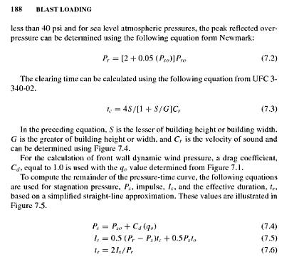
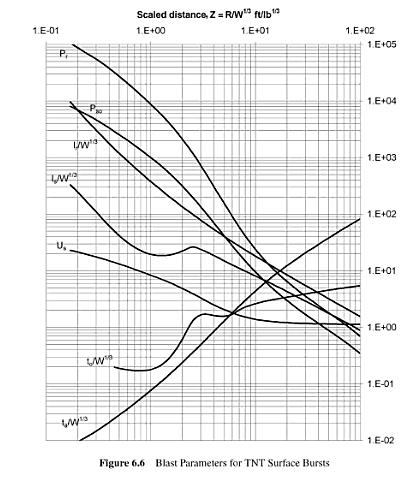
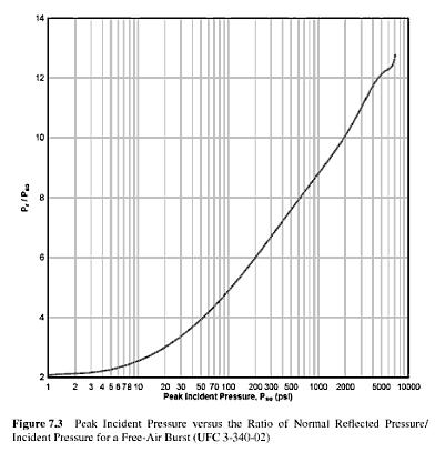
Blast Loading On Boundary Wall
Mahnoor Khawaja and 5 others reacted to UmarMakhzumi for a topic
I did a blast calc when I was in Pakistan for an embassy. Check the attached files. The other references that I have but cannot attach because of their substantial size are: Dynamic Loading and Design Of Structures-AJ Kappos Thomas Telford - Blast Effect on Buildings ASCE - Design Of Blast Resistant Petrochemical Buildings I got all this stuff from google searches, so would be easy to find it.(I can always email you the stuff let me know if needed) Thanks. Blast Barrier Design and Testing.pdf
 6 points
 -
Minimum Reinfocement Criteria For Crack Control
Ayesha and 5 others reacted to Badar (BAZ) for a topic
The statement taken out from ACI document only covers shrinkage cracks in reinforced concrete structures. Hence, it is regarding serviceability limit states. In order to fully understand it, one should know what they mean by 'acceptable level', or 'acceptable design limits'. There must be a paper regarding that, which needs to be studied. You should check latest ACI code; I think. they have not included this provision in the latest code. They are continuing older provision of 0.18/0.2 %. It look like as if they have not taken the recommendation of this committe seriously. It is a confusion.6 points -
Pre-Engineered Buildings
Engr1 and 5 others reacted to Muhammad Ali Dayo for a topic
Basic Building Parameters The basic parameters that define a pre-engineered building are: Building Width, Building Length, Building Height, Roof Slope, End Bay Length, Interior Bay Length, and Design Loads. BUILDING WIDTH: No matter what primary framing system is used, the building width is defined as the distance from outside of eave strut of one sidewall to outside of eave strut of the opposite sidewall. Building width does not include the width of Lean-To buildings or roof extensions. BUILDING LENGTH The longitudinal length of the building measured from out to out of end wall steel lines. BUILDING HEIGHT: Building height is the eave height which usually is the distance from the bottom of the main frame column base plate to the top outer point of the eave strut. When columns are recessed or elevated from finished floor, eave height is the distance from finished floor level to top of eave strut. ROOF SLOPE: This is the angle of the roof with respect to the horizontal. The most common roof slopes are 0.5/10 and 1/10. Any practical roof slope is possible. END BAY LENGTH: The distance from outside of the outer flange of endwall columns to center line of the first interior frame column. INTERIOR BAY LENGTH: The distance between the center lines of two adjacent interior main frame columns. The most common bay lengths are 6 m, 7.5 m and 9 m. DESIGN LOADS: Unless otherwise specified Steel pre-engineered buildings are designed for the following minimum loads: Roof Live Load: 0.57 kN/m2 Design Wind Speed: 110 km/h Design for snow loads, earth quake loads, collateral loads, crane loads or any other loading condition, if required must be specified. Source: zamilsteel.com6 points -
Safe Punching Shear Problem
EngrJunaid and 5 others reacted to WR1 for a topic
well i dont believe SAFE gives wrong results as compared with manual calculations.. and here im talking about SAFE 12 But you have to consider following things:- 1) check the load size for perimeter calculation 2) apply the correct parameter for location of column...For example if it is interior column , select the point goto Design>Punhcing Overwrites and make it interior 3) Make correct cover settings. Goto Design> Design Preferences and put the correct cover and bar size 4) Make sure you are familiar with the load combos for which you will design your structure or punching After analysis, right click on the point of column you will see detailed calculations for punching and the governing combination. Make sure SAFE 12 is calculating the effective depth and the perimeter correct which will surely be correct if you follow above steps. You can also check punching calculations of other non governing combinations.6 points -

Job Places
umair siddiqui and 5 others reacted to Shahjahan for a topic
i am working for the installation/execution/construction of over head transmission lines. it is only good for those who can travel minimum 300 km/day, believe in long distance relationships and having only half of brain active. for consultancy, the issues are very technical and are very romantic to handle6 points -
Etabs/sap2000 Dome Geometry
Tayyab Zafar and 4 others reacted to UmarMakhzumi for a topic
Posting this thread to break the ice. Modelling domes is very easy in Etabs/SAP. All you need to do is to draw the curvature of the dome in elevation by a series of straight lines, but draw only the one half. Then using the apex at centre point, radially extrude the line say 24 times at 15 degree intervals (or 48 times at 7.5 deg intervals. This feature is under Edit> Extrude Lines to areas. You can further use this geometry for Finite Element Analaysis. 5 points
 -
The Most Common Errors In Seismic Design & Their Avoidance
UmarMakhzumi and 4 others reacted to EngrUzair for a topic
Dear colleagues, The following article describes some of the most common errors, we may make while carrying out seismic design in accordance with ASCE 7-10 and IBC 2012. It also guides us how to avoid these errors in our future designs. http://www.structuremag.org/wp-content/uploads/2015/08/C-StrucPerform-Heausler-Sept151.pdf A somewhat different version of above article, is available at the following link: http://seaoo.org/downloads/NCSEA_Conf_Info/2014_ncsea_common_errors_in_seismic_design___how_to_avoid_them._t._heausler.pdf Regards.5 points -
Beam/column Capacity
Ahsan Kazmi and 4 others reacted to Badar (BAZ) for a topic
It means you need to increase, or decrease, reinforcement in beam, or column. But, You have to have a reinforcement which satisfies your elastic elastic analysis. You can't reduce the reinforcement, below the level required for resisting factored combos, to satisfy this provision. You need to add more, or reduce. But reduced moment capacity of that member should satisfy the forces of design combos. If you have provided more reinforcement than the requirement of elastic analysis, you will need to check the shear corresponding to probable moment strengths. Increase in moment capacity of member will lead to an increase in seismic-shear. I hope, I have answered your query.5 points -
Use Of Mass Source Command In Etabs
Mazhar Amin and 4 others reacted to UmarMakhzumi for a topic
Like Rana said, I will just add one more thing. I remember that Live Load only needs to be considered in Mass Source if its a warehouse, or LL=100psf or more. See UBC, for clarification, there is something about the warehouse or 100 psf requirement.5 points -
Property Modfiers_Etabs!!!
khalid and 4 others reacted to UmarMakhzumi for a topic
here is an excerpt from on of my fav books on structural design, I read it some 3 years back, and it always reminds me how we structural engineers can exploit material properties to achieve robust designs.5 points -
Property Modfiers_Etabs!!!
Junaid Farooq Janjua and 4 others reacted to Badar (BAZ) for a topic
membrane is capable of taking tensile stresses only like our skin or tarpal (urdu word). Word slab used in structural engineering cant be membrane. shall is capable of taking shear and moment. Any thing that can take shear or moment can also take direct tension or compression. plate is shell/slab loaded in its plane like shear wall.5 points -

Intro (Ali Ahmed)
Mahnoor Khawaja and 4 others reacted to engraliahmed for a topic
I am Ali Ahmed, working as lecturer in University of Engineering & Technology, Lahore. I have completed my MSc Structural Engineering from the same university. I was the topper of my BSc Session (2004) & won four gold medals. Along with the lecturer-ship I am also participating actively in different research projects being carried out in UET Lahore.5 points