kHURRAM ALI
-
Posts
49 -
Joined
-
Last visited
-
Days Won
5
Content Type
Profiles
Forums
Events
Everything posted by kHURRAM ALI
-

Reading the drawings in SAFE
kHURRAM ALI replied to Tyrion.Lannister's topic in Spreadsheets & Softwares
i think BC means bottom contineous , BE means bottom extra , similarly TC and TE means top contineous and top extra -
what modifiers are you taken , 0.7 (uncracked) or 0.35 (cracked) , you have to check first your shear wall stresse with rupture stress fr=7.5(f'c) in psi , if wall stresses exceeds from fr than you have to take wall as a cracked section i.e 0.35 modifier otherewise 0.7 is o.k , as per ubc code. when wall modifiers changes from 0.7 to 0.35 , make wall to attracts lesser forces , by which its starts to pass in shear , but it depends on how much force is taken by shear wall
-
I have done some calculation , after review some book , any comment would be appreciable drift check.pdf
-
use staggered bar detailing at lap joint , by doing this , you can provide 5.25% steel in column instead of 4%, at lap joint column steel from above story will be half , so total steel at lap will be 5.25+5.25/2= 7.875% , which is less than 8% for IMRF . This detailed not applied to SMRF , as code restricted max column steel < 6%

-
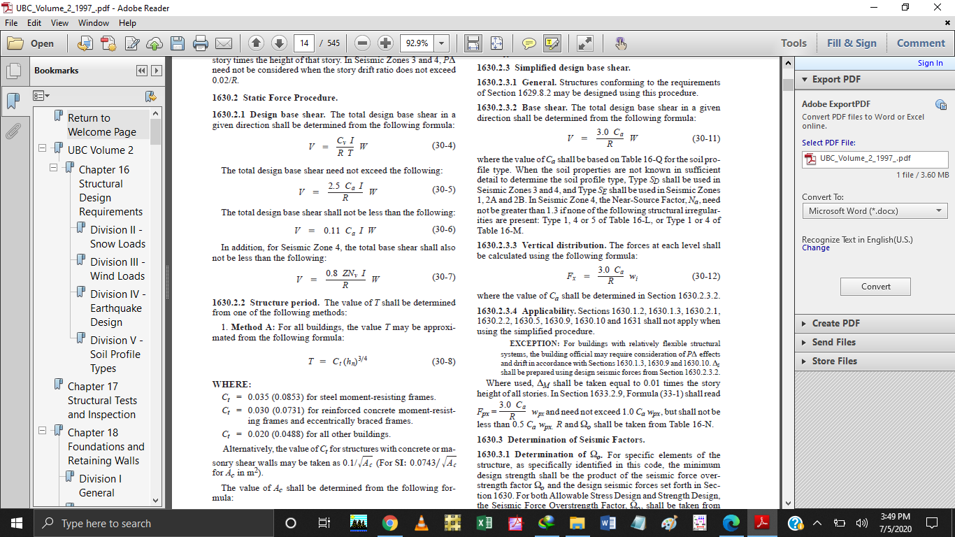
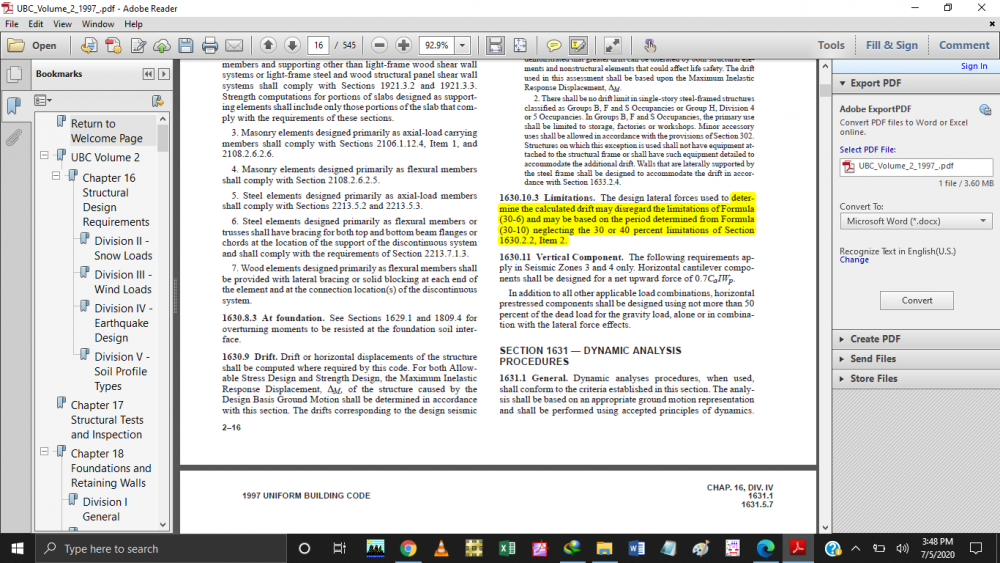
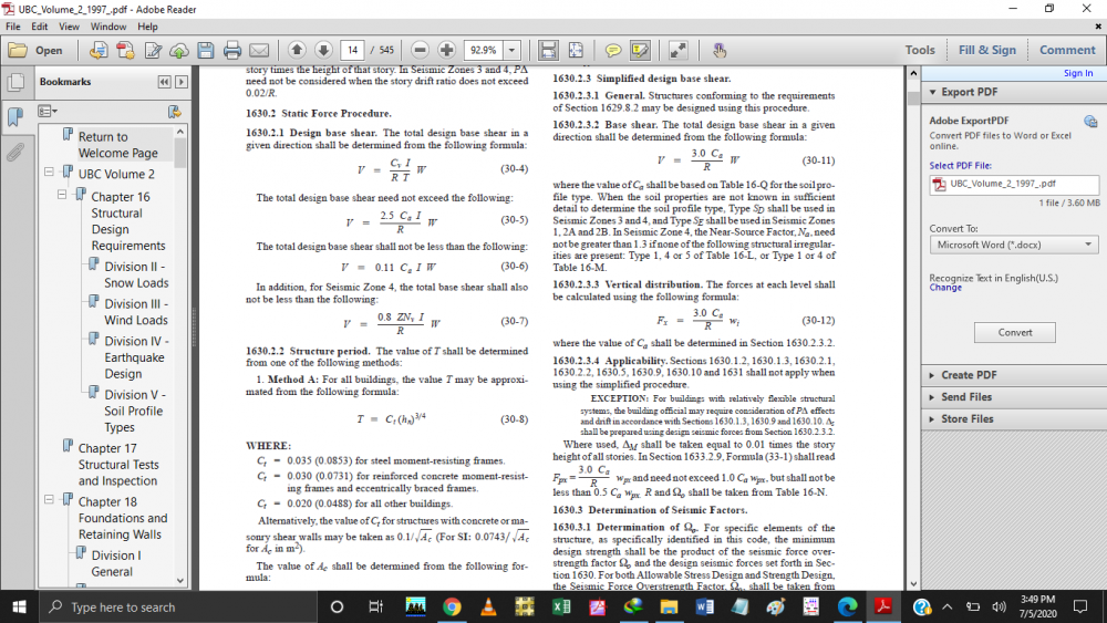
Aslamwalekum to all, Building base shear as per UBC is calculated from equation 30-4 to 30-7 as shown in first image , but for drift it allows to ignore eq 30-6 as shown in 2nd image and calculate base shear on time period of Method B eq (.30-10) . My question is if model a building in ETABS , It calculate base shear from equation 30-4 to 30-7 , so how can i make ETABS to ignore eq (30-6) for drift calculaton only.
-
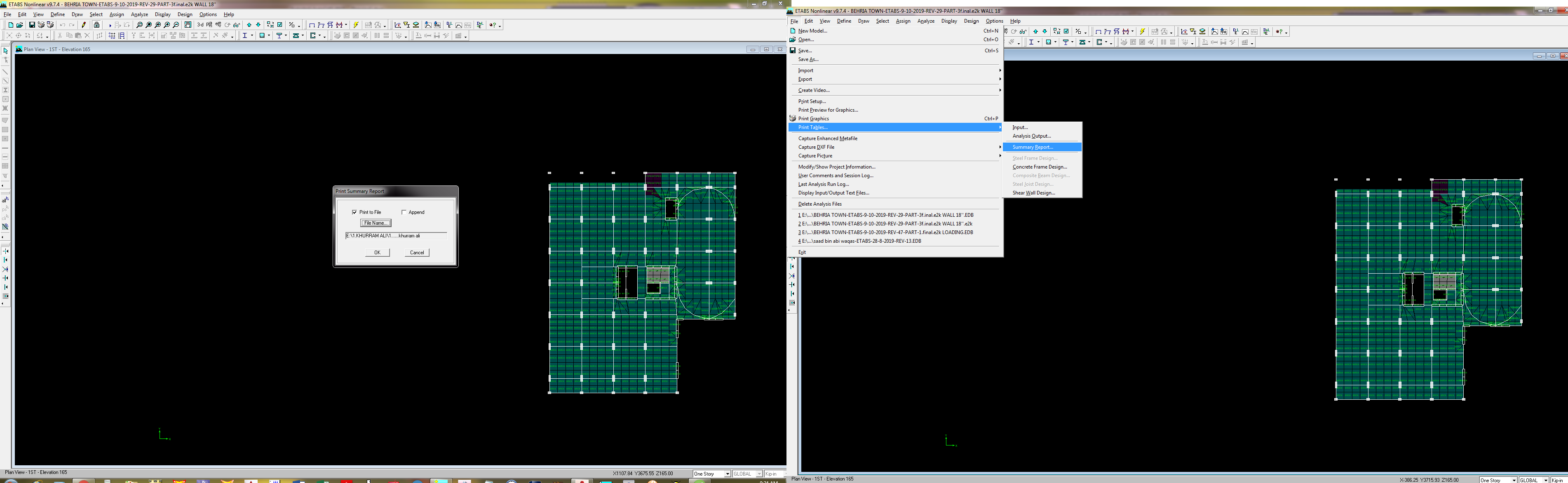
Sorry , i was looking at print table summary report , but yes you were right it shows in print table input options thanks
-
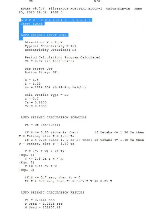
Dear asad Thanks for reply , unfortunately i am using ETABS 9.7.4 , which dont show this option , please see attached image , i will great full to you, if you help me with this version

-
Aslamwalekum to all, I want to check my building base shear , ETABS give its calculation in summary report which is shown in attached image but, in few models it dont show these calculation , can somebody review it and suggest what is the problem in my model. the ETABS model and its summary report is attached with it BEHRIA TOWN-ETABS-9-10-2019-REV-47-PART-1.final.e2k LOADING.txt BEHRIA TOWN-ETABS-9-10-2019-REV-47-PART-1.final.e2k LOADING.rar
-
As per our office practice, we add shear r/f with torsion , for flexure we divide torsion r/f by 2 , then add this r/f in top and bott longitudinal r/f
-
its now in the preference override option
-
if you want to model a beam as simply supported beam , then you will need to end realese , so the beding moment draw as for simply supported beam, other wise without relase , depending upon the stiffness , negative and positive both moments comes in beam
-
IBC code use instead of UBC 1997 in karachi
kHURRAM ALI replied to kHURRAM ALI's topic in Seismic Design
you can download from below link https://de.usembassy.gov/wp-content/uploads/sites/21/2016/08/Attachment-J.2-2015_OBO_Building_Code1.pdf -
IBC code use instead of UBC 1997 in karachi
kHURRAM ALI replied to kHURRAM ALI's topic in Seismic Design
i found useful info on obo building code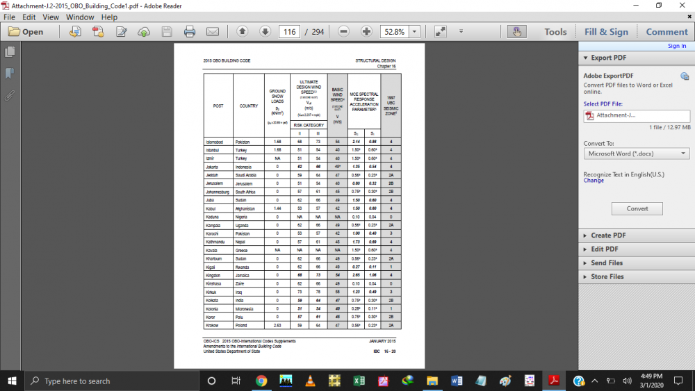
-
Eqution for calculating bearing capacity
kHURRAM ALI replied to muneeb1213's topic in Foundation Design
commonly raft have bearing capacity on 2in settelement , while isolated footing have bearing capacity on 1 in settlelemt, so diifinitely bearing capacity at 2in settlement would be greater than bearing capacity at 1inch settlement- 3 replies
-
- 1
-

-
- bearing capacity
- foundation
- (and 1 more)
-
Improve Bearing Capacity of Soil
kHURRAM ALI replied to Muhammad Ameen Ali's topic in Concrete Design
stone column and vibro compaction are the techniques use in my city (KARACHI), but the technique depends on soil condition -
Aslamwalekum to all, I am designing a building located in karachi , which lies in zone 2B , soil type Sc as per pakistan building code (PBC) , from (PBC) i extract seismic parameters like Ca and Cv , but when i switch to IBC it required seismic group, Ss , S1 , site class e.t.c , all these parameters can extract from IBC , but for karachi there is no info available, from which i can get these parameters , so how do i find these parameter for my design , is there any correletaion between UBC and IBC parameters by which i can extract these , please help thanks
-
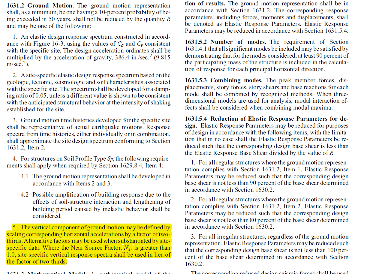
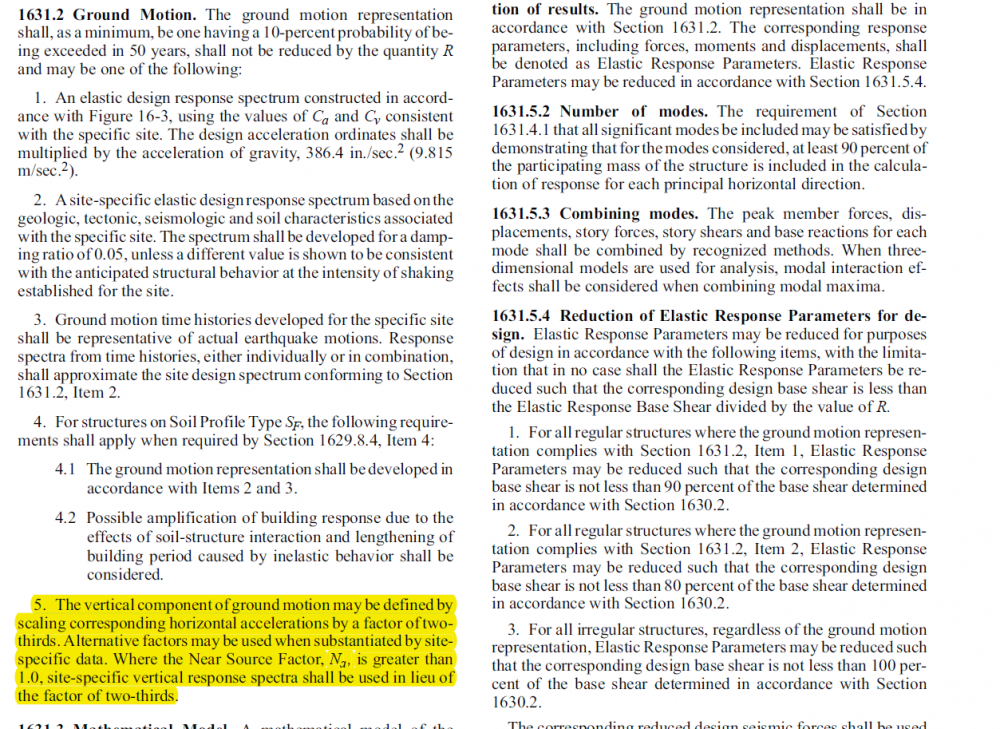
Aslamwalekum , The above refrence is taken from UBC 1997 , I am desing a 33 story building, in Zone 2B , the building have irregularities , for which i need to perform dynamic analysis , my question is when do i need to add Vertical component of ground motion response spectrum, as mentioned in image, I use response spectrum in X and Y direction with scale facotor , but for Z direction it says to take 2/3 of scale factor of X and Y direction response spectrum I belive that it should done for zone 3 and zone 4 , but for zone 2 and 1 should i have to use this , please guide point 1 ETABS.pdf
-
I had run a model in ETABS v 16.2.1 , design a shear wall with “uniform distribution”. I got design summary in which vertical steel in percentage was 1.68% , also it is required to provide boundary zone length of 49.7 in. Then i ran ETABS detailer and bring out shear wall detailed steel drawing. I found that steel at middle length of wall was approx. same as ETABS summary , but steel provided in boundary zone was not shown in design summary, it only gave boundary zone length, so where ETABS showing this steel in design summary , or I have to calculate it some how. Please see attached image for further clarification, model is also attached. Thank you. wall.$et wall.EDB wall.pdf
-
load combination for pick up shear walls
kHURRAM ALI replied to kHURRAM ALI's topic in Software Issues
thanks for the response , if my system is not dual , than i need to boost up factors to provide 25% shear to column , the problem is that i have pick up shear wall also , the columns that support these walls need to design for special load combination 1.2D.L + 0.5 L.L + 2.8 E.Q , so do i need to enhance this speacial combo also , like 2.8 E.Q to 3 E.Q. pardon me for wrong reference , it was not in the code , it was in taranath book, that it should be design for axial load , see the attached file SWScan01179.pdf SWScan01180.pdf -
if both beam have same stiffness (same size , same strength) , same span and same loading than , then there will be no secondary beam , both of them will act as primary beam . this system is called grillage system
-
Dear all , aslamwalekum when there are pick shear walls introduce in building , then due to vertical irregularity , we need to design the supporting column on special combo "1.2 DL + 0.5 LL +/- 2.8 EQ" , IF building is design for dual system , i want to know that how can i implement this in etabs , should i just make this combination, run and design the model and check supporting column or there is another procedure . I also read on code that supporting column should design for axial load only , but in etabs it consider axial + moment at "1.2 DL + 0.5 LL +/- 2.8 EQ" combo , so how do i avoid moment . will end release the column can work? Another issue i want to highlight that , if my system is not dual , for e.g columns are taken 20% base shear , so i need to boost up EQ by 5% to make it dual , so do i have to boost up speacial combo "1.2 DL + 0.5 LL +/- 2.8 EQ" also or should i just check it seperately. many thanks in advance for reviewing and sharing your knowledge on the topic
-
HOW CAN I GET THESE VALUES IN ETABS
-
aslamwalekum to all, when we need semi rigid diaphragm , i normaly take rigid diaphram for beam slab system , i got a vetting project (model made on ETABS 2016) , in which flat slab are used and semi rigid diaphram is assign , A/c to IBC 2006 , concrete slab with thickness more than 1.5 in , not consider as flexible diaphram , here is the code refrence. ''''''''''''''''''''''''''''''''''''''''''''''''''''''''''''''''''''''''''''''''''''''''''' 1613.6.1 Assumption of flexible diaphragm. Add the following text at the end of Section 12.3.1.1 of ASCE 7: Diaphragms constructed of wood structural panels or untopped steel decking shall also be permitted to be idealized as flexible, provided all of the following conditions are met: 1. Toppings of concrete or similar materials are not placed over wood structural panel diaphragms except for nonstructural toppings no greater than 11/2 inches (38 mm) thick. 2. Each line of vertical elements of the lateral- force-resisting system complies with the allowable story drift of Table 12.12-1. 3. Vertical elements of the lateral-force-resisting system are light-framed walls sheathed with wood structural panels rated for shear resistance or steel sheets. 4. Portions of wood structural panel diaphragms that cantilever beyond the vertical elements of the lateral- force-resisting system are designed in accordance with Section 2305.2.5 of the International Building Code ''''''''''''''''''''''''''''''''''''''''''''''''''''''''''''''''''''''''''''''''''''''''''' here in my case slab is 8 in thick , so can it be act as flexible diaphragm. i belive for metal decking , i can use semi rigid diaphram , but not for 8 in thick flat slab
-
ASLAMWALEKUM IN ETAB MODEL THE SECONDARY BEAM BREAK ON PRIMARY BEAM ,SO THAT POINT LOAD OF SECONDARY BEAM CAN APPLY ON PRIMARY BEAM , BUT IF TWO BEAMS OF SAME STIFFNESS , SPAN AND LOADING ARE INTERSECTING AT THEIR MID POINTS , HOW TO DECIDE WHICH ONE WILL BE PRIMARY AND SECONDARY BEAM , I AM ATTACHING THE ETABS PALN

-
i have posted a few lines mention in the ACI 318 code refrence R10.10.4.1 below ,please review and confirm for 43% increase in service modifires , i belive drift is also a kind of deflection and deflection always calculate at service level , thats why i think for drift modifiers will not be same as they use for ultimate design the code lines are Section 10.10 provides requirements for strength and assumes frame analyses will be carried out using factored loads. Analyses of deflections, vibrations, and building periods are needed at various service (unfactored) load levels10.37,10.38 to determine the serviceability of the structure and to estimate the wind forces in wind tunnel laboratories. The moments of inertia of the structural members in the service load analyses should be representative of the degree of cracking at the various service load levels investigated. Unless a more accurate estimate of the degree of cracking at service load level is available, it is satisfactory to use 1.0/0.70 = 1.43 times the moments of inertia given here for service load analyses.