

EngrUzair
-
Posts
475 -
Joined
-
Last visited
-
Days Won
242
Content Type
Profiles
Forums
Events
Everything posted by EngrUzair
-
 AA. Following links & publications may be helpful in this regard: 1. Structural design for substations (https://www.eng-tips.com/viewthread.cfm?qid=492373) 2. ASCE Manual 113 (2008) Section 3.1.8 3. IEEE Standard 605 4. Reevaluation of IEEE Standard 605's Calculation of Short Circuit Force on Rigid Busbar Structures (https://www.epri.com/research/products/1021917) Regards.
 -
AA. Soil bearing capacity is provided by the client in the shape of site-specific soil investigation report (SSSIR), prepared by a geotechnical engineer for the site area where building is to be constructed. If SSSIR is not available, client should be asked to arrange the same for proper design of foundation. Regards.
- 1 reply
-
- 1
-

-
Assalamo alaikum! Good quality seismic hazard maps of BCP-2021 and Tabulated values of Short-period Spectral Acceleration Ss & Long-period Spectral Acceleration S1 etc. for major cities of Pakistan, are available at this Link. Regards.
-
Assalamo Alaikum! Building Code of Pakistan 2021 edition has been printed. PDF version of the same is available at the following link. https://drive.google.com/file/d/154K6RIJ0QZJCJ0Q4HsYl-KVqMuJZZF_o/view?fbclid=IwAR3mWSF1X5xBWywdz3-l1kKt7C4HSQi6D4RYZ5RMS0q-eRZ9GGIj8-vJEUk Regards.
-
AA. Link of a catalogue, providing information about cross-sectional details & weights of different types of steel shapes available in Pakistan, is given below. It also contains list, thicknesses and weights of plain and corrugated steel sheets. Moreover, information about steel door chowkhats is also given therein. Shared for the benefit of all those interested. Regards. Link:- https://www.mwpbnp.com/downloads/Catalogue-mwpbnp.com.pdf
-
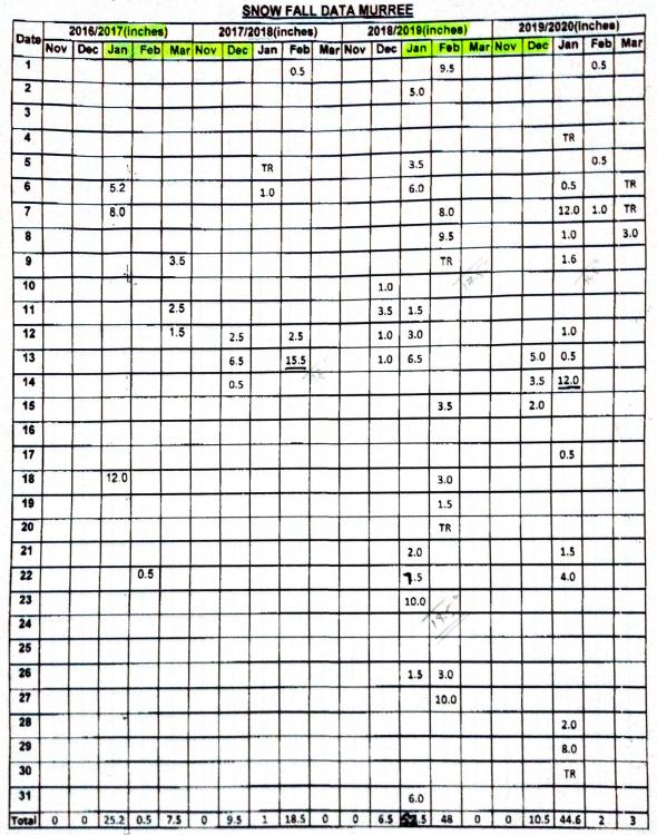
AA. Snowfall data of Murree, for the period from Jan 2017 to Mar 2020 has received. It is attached below for the information of all those interested. Data for the earlier period has already been uploaded in a previous post. Regards.
-
AA. Depending upon whether you want to follow American or European codes, following references might be helpful in learning the design of bridges: 1. Based on American codes a. Design of Highway Bridges_An LRFD Approach by Barker and Puckett b. AASHTO LRFD Bridge Design Specifications c. AASHTO Guide Specifications for LRFD Seismic Bridge Design d. Design of Modern Steel Railway Bridges by Unsworth e. AREMA Manual for Railway Engineering (MRE) 2. Based on European codes (Eurocode) a. Designers Guide to Eurocode 1_Actions on Bridges b. Designer's Guide to EN 1992 Eurocode 2 Design of Concrete Structures Part-2 Concrete Bridges c. Designers' Guide to Eurocode 8 - Design of Bridges for Earthquake Resistance EN 1998-2 d. Bridge Design to Eurocodes Worked examples (European Commission Joint Research Centre) Regards.
- 1 reply
-
- 2
-

-
-
- bridge
- structural design
- (and 1 more)
-
There is a large difference between section properties of the required and the available steel girders. Required major section modulus Sx is 3.63 times that of the available girder. It means that capacity of the available girder has to be increased to about 4-times its present capacity. It might not be an easy or even cost effective task.
-
Check out the following books:- 1. Ground Improvement by Kirsch and Bell (CRC Press) 2. Principles and Practices of Ground Improvement by Jie Han (Wiley) 3. Soil Improvement and Ground Modification Methods by Nicholson (Elsevier) 4. Ground control and improvement by Xanthakos et al. (John Wiley and Sons) 5. Ground Improvement Techniques by Purushothama Raj Regards.
-
Modelling of different building portions in a single model might be necessary to safeguard against seismic pounding of adjacent building portions, in certain conditions (e.g., different heights, varistion in stiffnesses, insufficient gap) More details, regarding pounding effect in buildings, are available at the following Link.
-
You will need to try a column having a larger cross-sectional dimensions. It should not be hard to manually calculate the required column size, using the required axial compression capacity, according to the applicable material design code.
-
It would be better to include the different portions of the building, separated by expansion joints, in a combined model as well, in order to study the behavior of structural elements located adjacent to expansion joints. For this purpose, the members (columns etc)across the expansion joints may be connected through provision of a strip footing or a raft.
-
Warnings are clear in details (i.e. type of warning & their locations). You need to correct the problems mentioned in the warnings, through merging or deleting/redrawing the members or elements, one by one. In the essence, there should be no warning message, on using Check Model command. Otherwise, the structure would not be correctly modelled.
-
Autodesk Revit is in fact not a structural software. Rather, it is a software used mainly for saving architecture & construction related building information (for example, 3-dimensional building layout, wall & floor types, finishes etc.), in order to visualize the building geometry, preparation of bills-of-quantities and control construction related activities. Revit does not carry out structural analysis or design directly. The geometrical & loading information from Revit however can be exported to Autodesk Robot software for structural analysis. Revit may be very useful in architecture, estimation and construction fields, but, not in the structural analysis or design. Because, the quantum of structural output obtainable from Revit is not worth the time and effort required to model the whole structure in Revit for getting some structural output. Structural modelling otherwise can be done more easily & speedily. Therefore, IMHO, there is no use of wasting time on learning Revit, in case you are interested in structural analysis & design only. HTH Regards
-
The settlement is likely due to weakening of soil support beneath the columns. There may be several reasons for this, like ingress of moisture in the underneath soil, sudden subsidence of some underground cavity etc. This may be investigated through some geotech engineer. Underground water tank, some nearby leaking water supply or sewerage line might also be the reason for weakening of the soil. To start with, these should also be checked & any leakage observed should be promptly & properly rectified. Futher advice can be given on knowing the results of geotechnical investigation, carried out for determining the most likely cause of settlement.
-
PEB structures are a special type of steel structures. These are less common in our country, as compared to RC structures . Accordingly, very few firms or structural engineers design these structures. Some locally known such firms include Zamil Steel, PEB Steel, Mammut, Izhar Steel etc. Larger firms have their own design manuals (and in some cases, their own special software as well), which you may search on the internet. UmarMakhzumi has pointed out to the proper source & authority dealing with this type of structures. Analysis & design of PEB structures is similar to normal steel structures. However, MBMA Manual provides better design aids (based mainly on ASCE 7), especially with reference to application of wind loads to this type of steel structures. In addition, it has several detailed wind analysis examples dealing with Enclosed, Partially Enclosed & Open type steel buildings. This manual will be a very useful source for understanding the design of steel & PEB structures covered in MBMA , in case you already have a good command on the use of AISC Manual of Steel Construction.
-
In case of Lumpsum contracts, Unit Rates are required for the following purposes:- a. For calculating the cost effects of deviations or variations of quantities, when the variation is beyond a certain limit b. For calculation of payment for any additional similar work, if required or ordered in connection with the same contract. c. For determining the payment amounts in case of Items of work for which actual quantities are unknown at the time of tendering. These items are included as 'provisional items' in tender documents. HTH Regards.
- 1 reply
-
- 1
-
-
WA. Checking this link, you might be able to get your required information.
-
sloping ground Seismic Analysis on Sloping Ground
EngrUzair replied to ZAFAR GOLCONDA's topic in Seismic Design
Very informative review paper. Thanks for sharing. -
Yes. Why not?
-
Florida Bridge Collapse
EngrUzair replied to UmarMakhzumi's topic in Engineering Marvels & Disasters
Thanks Umar, for sharing the news. Real reason behind this collapse would be known in future sometime. It may be due to some structural design discrepancy, some overlook during the construction phase design, or something unusual happening with the structure after completion of construction. However, this type of disasters in an advanced country like USA, where engineering design & construction procedures and practices may be termed state-of-the-art, remind us (the engineers) to be very very careful during both the design and the construction phases of a public facility, in order to avoid such disasters in future, to safeguard loss of valuable lives & to avoid a bad name for the engineers community. -
Forum Update
EngrUzair replied to UmarMakhzumi's topic in Website Announcements/ Problems/ Login/ Registration Issues
Congratulations to both @Rana and @BAZ . Although they have more responsibility now. However they are very responsible already. -
Firstly, conversion of reinforcement area for flexural (longitudial) beam reinforcement to 'number of bars' is similar to that for the vertical reinforcement of columns. However, for deciding the 'number of bars provided' in case of beams, we round the calculated value to next higher integer number only, whether it is even or odd. For example, if required steel area is 0.9 sq.in., and #5 bar is to be used, then required number of bars =0.9/0.307=2.93. In this case, we may use 3 #5 bars for the beam. (Whereas, in case of a square or rectangular column, we needed to use at least 4 bars.) Secondly, in case of a beam, required number of bars are to be provided along the relevant (top or bottom) face of the beam only, depending upon whether we are detailing the reinforcement for the negative or positive bending moment. In case, required number of bars (as calculated in previous paragraph) exceeds the maximum number of bars permissible in one layer, required number of bars will be provided in layers, separated vertically by spacers. Thirdly, total area of reinforcement provided, must be within the steel areas corresponding to Minimum & Maximum steel ratios prescribed by ACI 318 for the beams. Fourthly, detailing of all type of beam reinforcement needs be in accordance with relevant provisions of ACI 318 and ACI 315 (whether seismic or non-seismic, as applicable). Out of three reinforcement values shown along (the top or bottom side of) a beam, two outer values (0.9 & 0.9 at left & right sides of top face, and 0.6 & 0.4 at left & right sides of bottom face of the beam under discussion) indicate the amount of reinforcing steel required at the relevant (top & bottom) faces of the two supports. Whereas, the middle values (0.2 on the top, & the 0.6 on the bottom side) indicate the amount of reinforcing steel required at the mispan of the beam, on the top & bottom faces respectively. HTH Regards.
-
When the amount of required area of vertical reinforcement for a column is known (as we normally obtain from structural software like ETABS & SAP2000 etc.), its detailing involves following steps: a. Converting the reinforcement into number of bars. Actually required number of bars is calculated by dividing the area of reinforcement by the area of different bars one by one. For example, in the stated case, required number of bars for a #6 vertical bar (bar cross-sectional area=0.44 sq.in.) will be 4.5/.44=10.22 bars. For a #5 bar (bar area=0.307 sq.in.) will be 4.5/.307=14.6 bars. Similarly, for a #8 bar (bar area=0.785 sq.in.), required number of bars will be 4.5/.785=5.7 bars. b. Selecting the number of bars to be provided. Following are the important points to be considered while deciding 'bar size' and 'number of bars provided'. (1) Number of selected bars is generally an even number. For square or rectangular columns, minimum 4 vertical bars are required. Whereas for curcular columns, at least 6 bars are required. number.The 'number of bars provided' is obtained by rounding up the required number of bars to next higher even number. Based on calculations made in the previous paragraph, 12 #6, 16 #5 or 6 #8 vertical bars may be used to furnish a reinforcement area of 4.5 sq.in. in the given column. (2) The area of provided bars must be equal or a bit more than the required reinforcement area obtained from design calculations (or a structural software). (3) The configuration of selected bars & placement of ties within the column cross-section, should be in line with the following code provisions: i. ACI 315 Figures 13 and 14 (column bar configurations) ii. ACI 318-08 Section 7.7 (concrete cover requirements) iii. Applicable provisions of ACI 318-08 Chapter 21, keeping in view the seismic requirements & structural frame type. Regards.
-
It generally depends upon soil bearing capacity & will be recommended by the geotech engineer in soil investigation report (SIR) of a particular site. In case of non-availability of SIR, even for some nearby site, IMHO foundation depth should not be less than about 3 ft. Regards.
