EngrJunaid
-
Posts
62 -
Joined
-
Last visited
-
Days Won
22
Content Type
Profiles
Forums
Events
Everything posted by EngrJunaid
-
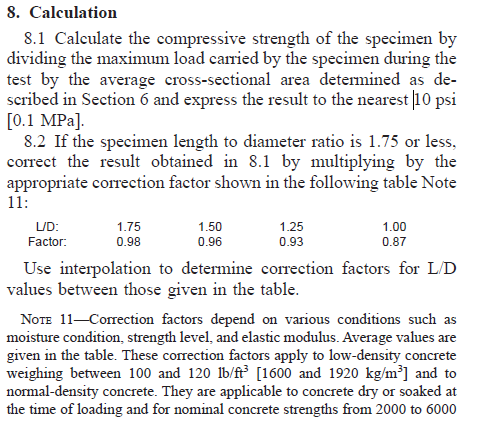
W.Salaam sir, If the specimen length to diameter ratio is 1.75 or less, Correction factor mentioned in ASTM-C39 will be applied. Please see the snapshot attached.
- 1 reply
-
- 1
-

-

NO LOADS TRANSFERED TO BEAMS/COLUMNS AFTER LOAD APPLICATION TO FLOORS
EngrJunaid replied to Kel's topic in Software Issues
Dear Kel, My comments based on a very quick review to your attached model are; 1)-Your load transfer issue is because you have provided joint fixity to each beam column joint at all floor level. By making all floor levels beam column joints free and fixing column at foundation level only will resolve your issue. 2)-Your model is showing more warnings of elements too close also. 3)-I would suggest you to improve your modelling, analysis, design and detailing skills in guidance of your in house seniors. Regards

-
Have a look to field practicing manual prepared after the 2005 Earthquake.
-
UBC 97 Response Spectrum Seismic Provisions
EngrJunaid replied to Ahmed Waqar's topic in Seismic Design
@jay olleta Code specify to use I*g/R value as initial scale factor. But the simple way is to Initially take the scale factor equal to 1000. Then run the analysis and check/compare the Static and dynamic base shear and update the scale factor accordingly. If Static Base shear is greater than Dynamic Base shear, you will need to scale up the dynamic Base Shear and if Static Base shear is less than Dynamic Base shear, you will need to scale down the dynamic Base Shear as follows: New Scale Factor=1000*(Static Base Shear/Dynamic Base Shear) See the UBC code pic attached for the minimum limit of reduction of elastic Response Parameters.
-
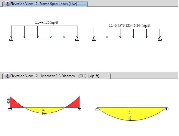
Dear @Saiful Islam Zaber Please see this link https://wiki.csiamerica.com/display/kb/Pattern+live-load+factor and the picture attached. Hope this will suffice your query.
-
Modelling of Retaining walls and BackStay Effect
EngrJunaid replied to Gerald Elusen's topic in Concrete Design
Include the wall in your model but play with wall stiffness modifier in order make it retaining wall. i.e use F12=0.001 to neglect the inplane stiffness of the wall. -
Modelling of Nicholson's Obelisk in SAP2000
EngrJunaid replied to Howard Roark's topic in Software Issues
The warning/error you are getting in ETABS shows that there is no line element in your model, only shell (area) elements and you are trying to display frame/pier forces etc.... Go to Display for displayinh shell stresses/forces... Share more detail about the subject model like base dimensions, height etc and a plane of your model/structure. -
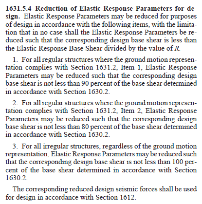
Yes you have to scale down as per 1631.5.4 (screenshot attached).
-
Calculating Partition Wall Load on Slab
EngrJunaid replied to Muhammad Munaf's topic in General Discussion
Wall Load per running foot = (Wall ht.)(Wall Thickness)(Unit wt.) Suppose you have 9inch thick wall of ht. 12ft and unit wt. of clay masonry brick is 120lb/cft. Wall Load/Rft =(12)(0.75)((120)=1080 lb/ft =1.08kip/ft Line load would not be assigned directly to area element (slab,wall). So assign a dummy beam and apply line load to this dummy beam. -
How to evaluate Vibrations in vehicle parking Reinforced Concrete building ?? Any code reference or procedure ???
-
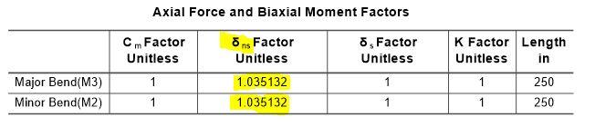
The quick method to check weather the design of slender column is fine or need to increase the column size are as follows; 1- In order to get the moments along column height accurately, divide the column into 2 or 3 segments. 2- Apply modifier. 3- Activate the P-Delta option from define menu. 4- Run the analysis and design with P-Delta and check the Non sway magnification factor i.e. delta(ns) in design summary of the column (see the pic attached). This delta(ns) must be less than 1.4. If this exceeds the limit of 1.4, increase the column size otherwise the column design is OK. Correction by seniors in my above steps will be highly appreciated.
- 4 replies
-
- 6
-
-
- column slenderness
- pdelta
- (and 1 more)
-
Sorry I replied in my previous comment regarding the application of copy, paste and replicate etc commands. hmmm now i get your point that you are worry about the copy, paste replicate etc short cut commands...... I checked both v13 & v16. These commands works in v13 and thats why they are shown there also. But these short cut commands are neither shown in v16 nor working there.
-
But some times there are bugs in the very latest versions. I would recommend not to use the very latest version. I usually use v13 for designing but also use the latest version for checking and application of new features of new versions.
-
Your model is LOCK, first unlock your model then they all will work smoothly.
-
Top and Bottom story range in STATIC LATERAL FORCE PROCEDURE
EngrJunaid replied to Fawad's topic in Seismic Design
If you are fine with all other serviceability checks then consider the torsion in your vertical member design. But keep your eyes on the separation gap between the blocks. The gap must be sufficient enough to avoid pounding action. You may run real time history (linear model) on your model for deciding the separation gap.- 4 replies
-
- 3
-
-
- backstay effect
- basement
- (and 2 more)
-
@Engr. Muhammad Salman share your model to check for the issue...
-
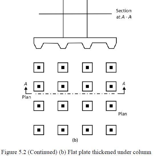
Dear all, Overall raft slab is 36" thick and i want to thicken raft upto 48" under the columns in order to control punching. So what is the correct way to model the extra 12" thickness under Columns in SAFE (See the attached Pic.) Option 1 : raft slab of 36" thick with MAT property and 48" thick slab with DROP property. Option 2 : raft slab of 36" thick with MAT property and 12" thick slab with DROP property and adjust the 12"thick drop slab level by using offset command. Then assign Subgrade modulus to both Raft slab and drop slab. Thanks.
-
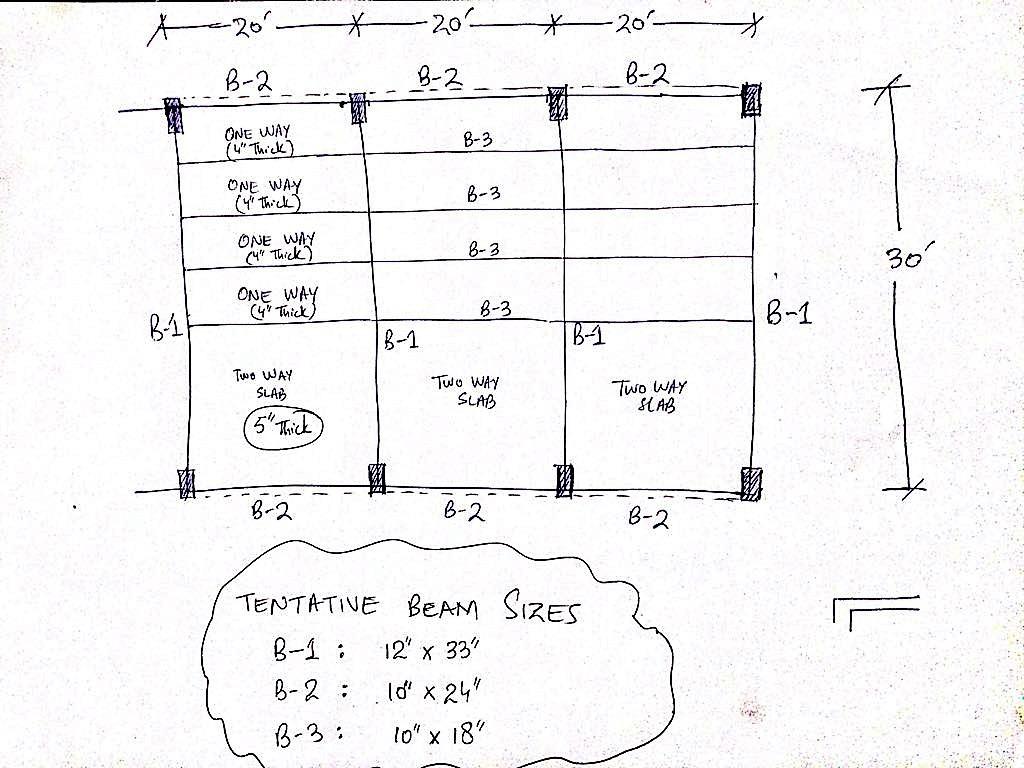
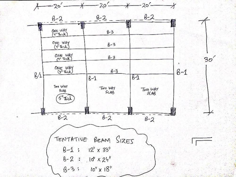
Dear Irfan, see the attach photo, I hope this will be the best structure scheme for your plan.
-
Yes i got your first reply was about steel structure and the document you share is very detailed and helpful. There will be 3 Machines each of weight 12 ton on first floor level. Till now i didn't get full detail about the machine vibrating frequency and other operational data from the client.
-
Thank you @Ayesha for your kind response. This will be Reinforced concrete building. I am worry about the effect of machine vibrations on floor Slab and fatigue stresses caused by the machinery. My question is how to consider the machine vibrations in design of RC Structures.
-
AoA, Hope you all will be fine and in good health. What factors, codes and limitations should be kept in mind while designing a two story (Ground+1) industrial RC structure. There are 3 machines (12-ton weight each) on first floor and about 120 psf is the area load. Thanks
-
Sir the simplest & easiest way of finding the area by its unique name is ETABS v13. Open your model in ETABS v13, go to Select ----> Labels -----> Shell Unique Name ----> enter the name of the required area.
-
Dear Sir, The option of selection any element by its UNIQUE NAME is available in ETABS v13 but unfortunately we don't have this selection option in ETABS v9. Display the meshing from set building view option and check the irrigular meshed area by right clicking on them for the effected area. All the WARNINGS are shown in the last Analysis Log with the global co-ordinates of the effected element. From those co-ordinates the area creating problem can be easily found. Thanks
-
Construction/Cold joint location in RC Column/walls
EngrJunaid replied to EngrJunaid's topic in General Discussion
Thanks & Jazakallah @EngrUzair Sir -
Construction/Cold joint location in RC Column/walls
EngrJunaid replied to EngrJunaid's topic in General Discussion
Thank you Waqar. I need code reference for this practice. Thanks