rummaan17
-
Posts
40 -
Joined
-
Last visited
-
Days Won
1
Content Type
Profiles
Forums
Events
Everything posted by rummaan17
-
Dear Umar, With reference to the example calculation in the design of blast resistant building. I have few queries. 1. What would be the case if Shear resistance is greater than bending resistance? its not explicitly defined in the guide. 2. If there is two way slab, what would be the case? 3. How are we comparing the strength of the section to applied load? does it has to with stand peak on side over pressure (Pso) or reflected pressure (Pr) for front wall. I am not clear about if section strength is compared to any loading . 4. If I model this scenario as Linear Time history analysis in STAAD and check support rotation limit of 2 degree. Is it correct. Thanks alot.
-
Dear Members, I am designing wall for blast load. I have came across several educational material that uses SDOF equivalent to design the same. If any body has past experience in modelling it in STAAD or ETABS and designing it ? Also, I have few question on SDOF calculation, If anybody has done it in the past do share.
-
Absolute or relative deflection in ETABS
rummaan17 replied to Hira Malik's topic in General Discussion
I believe deflection is a serviceability criteria and should be checked for global system, which I understand as absolute. -
Dear SEPakistan Member, I would like to know if there is any limit on Maximum Volume of concrete that can be cast in Raft Foundation in one go?Upto my knowledge, we cannot provide control/contraction joints in Raft. So how do we limit Heat of Hydration ? Reference would be much appreciated. Thanks.
-
Dear Mr.Rana, Thanks for your response. I just want to know in which case need to check the torsional irregularity ratio ?. I mean to check it in EQX and EQY only and then amplify the eccentricity in (X+Eccen Y, X-Eccen Y, Y+Eccen X, Y-Eccen X) . Am i right ??
-
Dear Umar, We should check the buidling drift ratio only in EQX and EQY right ? Not the one with eccentricity ?
-
Thanks Mr.Umar. Indeed a great help. Much appreciated.
-
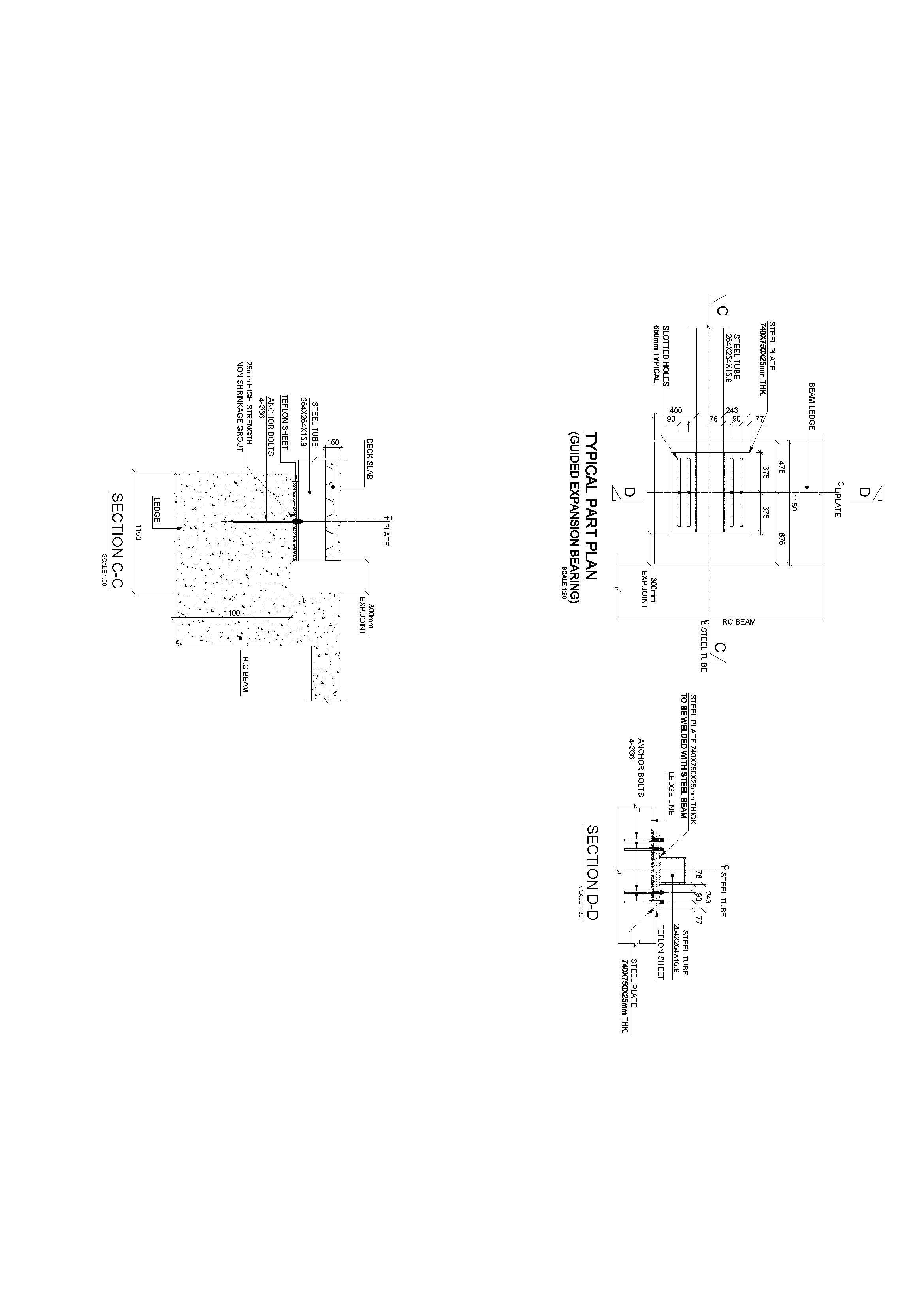
Thanks Mr.Umar. Its a ped way. Also, I am concerned about the movement of this pedway when buidling movies parallel to each other as this slotted hole doesn't account for it. Any idea ?
-
Find attached the sections.

-
Dear Mr.Umar Makhzumi. See attached image for detail.
-
Dear All, I have designed the bridge between two building. Fixed at one end and roller at the other. The bridge at the roller end, rests on a concrete ledge. I have provided the expansion joint based on the formulation of ASCE for building separation. I have certain queries on it : 1- Is building separation formulation is appropriate to provide expansion/moment joint in my case? 2- I am trying to allow the movement through slotted holes in base plate. If my bridge required expansion is 300mm through formulation indicated in Point-1 above, should the slotted hole be twice of it i.e. 2x300mm = 600mm I am still unsure as to what size the slotted hole should be ? and what governs the expansion joint of bridge over the ledge end. I am relatively new to bridges. any help would be highly appreciated. Thanks in advance.
-
Thanks alot Mr.Rana for taking time to explain it in such detail. i will act accordingly and let you know. My last concern if you could answer, this 0.25 value is coming from code ?
-
Dear Mr.Umar, Yes we have created some document for their timely response to our design but I guess we dont have any offical document from start that could justify this load application technique. Also Mr.Umar, certainly my review team never cease to surprise me as they argue over things that even doesn't make sense to me, who is a newbie in this field. Since, they are approving authority and we are tough on schedule we try to sort it out as they want. Secondly, i have some similar concerns. This 0.25 modifier track back to reference from code ? if any please guide me. I started using 0.25 modifier as I found this value on certain discussion on forums and after applying it I found the reinforcement to be just. but as you quoted, using two modifier at ULS state for two different load case ? how can we back it up. Any addition would be highly appreciated. Thanks in advance.
-
Thanks alot Mr.Rana . Indeed very useful. This thing was a pain for me since I have started applying temperature. At my last peer submission I finally realize that we should keep temperature model separate. There is also one more thing I figured out I was using Rigid daiphragm assumption at start which was resulting in very high axial forces in ETABS spandral. (ETABS doesn't design for spandral axial forces and designer has to check manually). I discussed with CSi Support about this and they told to use semi-rigid as temperature has no point with rigid daiphragm. Now, I use separate model with semi-rigid daiphragm for temperature which has decreased my axial load in spandral but has affected walls alot in terms of shear and flexure. Now what I understood. That i will keep a separate model with all WALLS and SLABS modifier =0.25 just for temperature analysis. Hopefully it will solve my problem.
-
Dear Mr.Umar, We have to submit our design for peer review which includes one international and one local consultant. I was amazed when they asked to apply load on overall structure. Even in my opinion its only outersurface that is most prone to temperature change, as here in middle east mostly building inside is temperature controlled. Though we also design slab for temperature change for all level, which i don't find just. I was getting high temperature stress even in slab which was then modified when I started using 0.25 modifier. The temperature reinforcement decreased drastically. I still consider SAFE as a better option to design as it consider temperature difference between top and bottom surface. But still shear walls remain a question, as if I decreased stiffness modifier of forces F11=F22 it will transfer all loads to column. Temperature load is applied in conjunction with other load combination as stated by ASCE 7-10 with loads factor not less than 1. Thats all I know about it uptill now.
-
Dear Mr.Rana, for negative temperature when we have compression will it have same modifier ?
-
There is alot of debate as what stiffness modifier to use F11=F22 for temperature. Previously, slab was getting high temperature reinforcement which was fixed using this value of F11=F22. Walls still have F11=F22=0.7 which is also a reason for high temperature load.
-
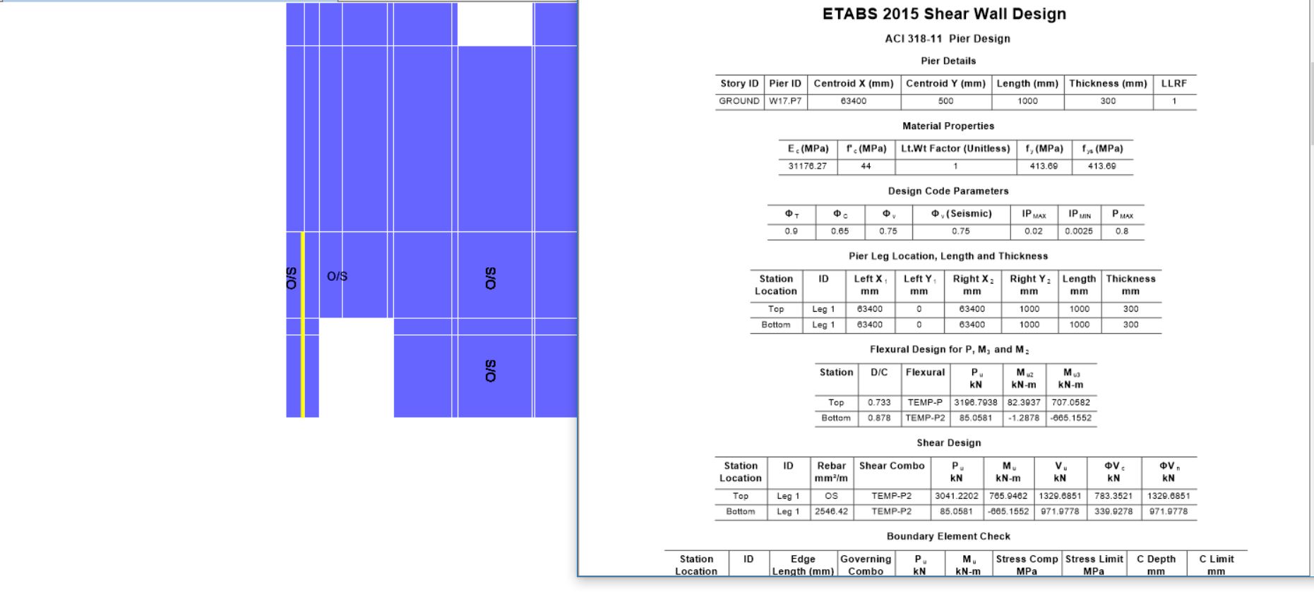
Dear all, I am trying to design shearwalls through ETABS with temperature load applied over shell. At various location, spandral section fails in Shear due to temperature and piers (sometime in shear, mostly in flexure). (See Attached Image) Certainly all the problem in Shearwalls are due to temperature. I don't want to increase cross section of spandral or pier at some location just due to temperature load case as it will appears non-uniform with rest of the wall. I have seen stiffness modifier affect distribution of forces and also rigid/semi rigid daiphragm assumption. Can anybody guide how to properly design the shear wall with temperature load applied in ETABS or share any similar experience. Thanks in Advance.


- 15 replies
-
- 1
-

-
- shearwall
- shearwall temperature
- (and 2 more)
-
Thanks Baz and ayesha for sharing your valuable opinions. Also, I found answer to my question as well also in ACI 318-14 as the least value of stiffness modifier that can be used to account for second order effect/Cracked analysis.
-
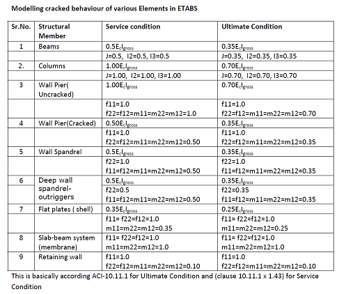
Dear Baz and Ayesha, Thanks for responding and keep thread alive. ACI 318-14 Table 6.6.3.1.1 (a) dictates the stifness modifier used in the analysis. ACI 318-14 6.6.3.2.2 indicates that for service-lad analysis these modifiers can be multiplied with factor 1.4 . Column/ Wall (Uncracked) = 0.7 x 1.4 = 0.98 = 1 Ig Beams / Wall(cracked ) = 0.35 x 1.4 = 0.49 Ig The picture I am attaching below Is from a design pdf of a renowed International consultant that I usually follow. I am open for further comments in this regards.
- 16 replies
-
- 2
-
-
- stiffness modifier
- cracked section
- (and 2 more)
-
Thanks UmarMakhzumi and Rana for help. Much appreciated.
-
Dear Baz, applying modifier takes into account the second order effect which Is also described by code. Building drift limit is mostly checked at serviceability stage with modifier 1 as it would represent un-cracked state. When a member crack in flexure or shear, most of the energy is dissipated. I guess its not correct to design the building for foces without consider rupture moment as it would be very conservative. The thing I am trying to have member input on is the flow of forces when stifness modifiers are used. Any addition would be appreciated. Thanks.
-
Dear baz, UmarMakhzumi, Actually, to be precise while designing Shear walls in ETABS alot of times we happen to meet un-usual behavior as some part of Pier and spandrel failing in shear near opening. We usually use 0.7 modifier for wall. I have seen if I lower down this stifness modifier value in the vicinity of opening, force get trasnfered and design become safe. Also. i have seen that this things work to certain extent only as after certain points we cannot transfer forces to other places. is this a correct approach to make some element crack before that other.
-
Dear Members, I would like to have your feedback on the use of stiffness modifier. We generally use the value dictated by ACI committee as to model the cracked behavior, which are Compression Member : Wall, Column, Pier = 0.7 Flexure Member : Beam, Spandrels = 0.35 Slab = 0.25 What if i want to use 0.5 for columns or 0.2 for beams. Are there any restrictions. I have played around with it on software like ETABS and noticed change in flow of forces as it transfer towards more stiff element. Your kind comments would be highly appreciated. Thanks
-
Dear UmarMakhzumi, What other columns are you looking for let me know. I have incorporated Translation and rotation in all three directions.