
.jpg.c0f3ad0ef57922aceb6ddba3017280bc.jpg)
Waqas Haider
-
Posts
190 -
Joined
-
Last visited
-
Days Won
17
Content Type
Profiles
Forums
Events
Everything posted by Waqas Haider
-
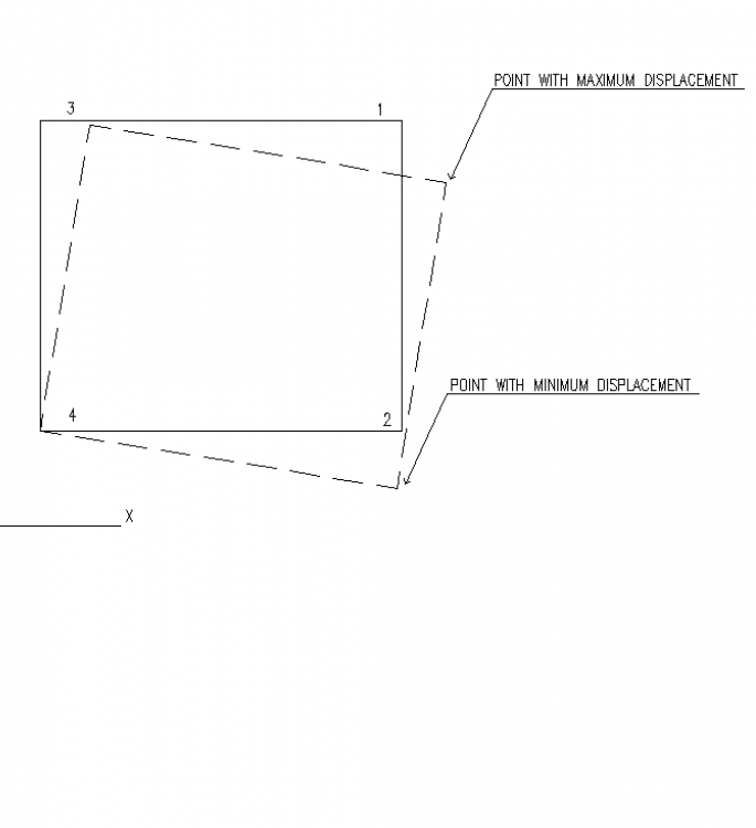
Assalam o alaikum. I have gone through previous posts regarding this topic but still i m unable to get the exact way to check torsional irregularity. What I have concluded through surfing and conversation regarding this topic with some of forum members, I m posting it with uncertainty that I have get it right or not. Kindly place your valuable comment. I m attaching a simple plan with the deformed floor shape under EQx loading with minimum eccentricity. I have labeled points. If X axis towards right, as marked in picture, For EQx loading with (say) 5% eccentricity, the following shape is gotten. Now UBC97 says, the building will be irregular if "Maximum story drift, computed including accidental torsion, at one end of the structure transverse to an axis is more than 1.2 times the average of the story drifts of the two ends of the structure ." My confusion lies specially in the bold part. Transverse to an axis (What axis) and two end of the structure (when two ends of structure)? Besides the confusion under wording, what i have been guided by other fellows is that, we need to check for EQx, the displacement of Point 1 under EQx drift combos (This will be the maximum displacement) and the displacement of Point 2 under EQx drift combos (This will be the minimum displacement). Then we need to compare the maximum displacement that is of point 1, to the average of this maximum and minimum displacements of point 1 and 2 respectively If this ratio is greater than 1.2, there will be torsional irregularity and if it is greater than 1.4, there will be extreme torsional irregularity. And we need to provide stiff columns or shear walls accordingly to reduce this ratio under 1.2 to eliminate torsional irregularity. Am i getting it right? Thanks.
-
.thumb.jpg.700916fbc7ead330085e15745d0270bd.jpg)
Ubc Seismic Drift Limits
Waqas Haider replied to UmarMakhzumi's topic in Journal/ Articles/ Tutorials
I think if Del.m is being compared, since it is maximum INELASTIC displacement, only collapse limit state will be satisfied and obviously damage and serviceability to structure will occur. Also we are designing structure to withstand seismic forces without collapse but damage is acceptable. -
how to model an internal hinge in frame in etabs/sap2000
Waqas Haider replied to Suveksa shrestha's topic in Software Issues
You can assign end releases for moment to beam connecting at a joint with column, for that joint specifically. This will model the end condition transferring all the forces except moments from column to beam end. -
Expansion joint in irregular building
Waqas Haider replied to Waqas Haider's topic in Concrete Design
Can u please refer me some reading material about it? Or only in code i can find required info about it. -
Expansion joint in irregular building
Waqas Haider replied to Waqas Haider's topic in Concrete Design
I have never applied temperature load in buildings. Kindly guide where can i find code guidelines about when it becomes necessary to apply temp load and how to apply it? -
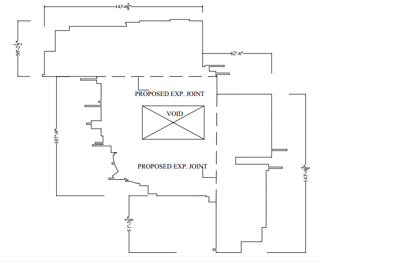
Assalam o alaikum, I m attaching plan outline of a building quite irregular in plan. As generally, expansion joint is provided at 150ft spacing, in my case, After 150 ft, The building changes its geometry and direction of plan so Cant Decide whether it needs an expansion joint or not. It also have a big void which is an open yard in the middle of building. If expansion joint is needed, i have also marked a proposal line. Does it seem ok? Building plan outline.pdf
-
I always follow the same method but while reporting of forces by etabs, it reports excessively high shell stresses near corners and joints? How to overcome this issue to get realistic value? What i did in last project i neglected the value of stress of bottom most plates near joints upto a distance equal to half thickness of the bottom slab. But i still doubt the value because it use to b higher than the manual calculations.
-
Assalam o alaikum, I need to design a college building located in zone 4 with 3 stories above ground and one basement completely buried. I have never worked with shear walls before so i m very much confused about location and design consideration of shear walls. I m attaching column and shear wall tentative layout for review from the seniors. Kindly review and put your valueable comments regarding location of walls and layout of columns. I also need to understand design of structures having frame as well as shear walls. What i know is this for zone 4, it will act as dual system with R value 8.5 and I need to satisfy all the conditions of 1629.6.5 of UBC. More over also tell whether can we provide openings for windows etc in shear walls? Thanks. To upload Model (1).pdf To upload.dwg
-
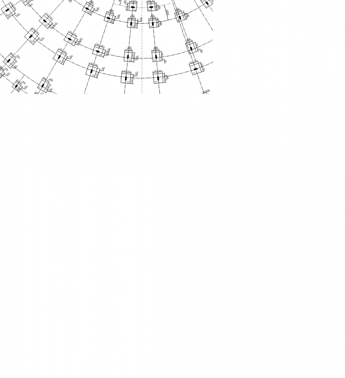
Assalam o alaikum, I am having a building with a semi circle shape. None of the footing is either parallel to global X-axis nor to the global Y-axis. The plan of footings is attached. The problem I am facing is, ETABS reports joint reactions along global X-axis and global Y-axis instead of along the local axes of column. Since my columns are at a degree to global axis, the joint reactions also becomes at a degree from column and footing. Since to use simple combined stress formula of stress = P/A + Mx*Y/Ix + My*X/Iy I need forces along axis of footing. Or i will have to resolve either moment of inertia of footing along direction of forces or vice versa, which is quite tough and time taking. The other option I can go for is to design footing in SAFE. But again here, there i dont find any option to rotate footing at a certain degree to match orientation of columns. If i rotate local axis of footing, It only rotates its local axes and meshing but not the footing physically itself. The orientation of footing remains same. How can i solve this problem? Either having reactions in etabs along local axes of columns can solve my issue so that i can design it manually or rotating footing in safe to match local axes of columns can solve my issue. So can any one guide me how to do either option? Thanks.
-
Consequences of incorrect meshing in ETABS
Waqas Haider replied to Ussama Waseem's topic in Concrete Design
Better u provide model and screen shots of ur plan showing meshing to give clear picture. -
brick mansonry Brick Mansonry design in ETABS
Waqas Haider replied to Rahulkld's topic in Journal/ Articles/ Tutorials
Brick masonry can not be designed in these software because brick masonry is neither the frame elements which can be modelled in these software nor are the simple isotropic type materials which can be modelled easily like area elements. You will have to do design for brick masonry manually. But you can take help from these software to read results of different type of analysis u need while doing manual design. There might be other softwares which can do this perhaps. But regarding these two softwares, i hold this opinion. -
RCC Basement vs Pillar Foundation for Home
Waqas Haider replied to BilalAhmad's topic in Concrete Design
Only exterior walls need to be of RCC. For construction purpose, U can consult the following manual. and MUST follow its practices. But remember, it is not the design manual. So you need to have a good design of your house including footings, RCC walls, band beams, and corner columns etc. -
RCC Basement vs Pillar Foundation for Home
Waqas Haider replied to BilalAhmad's topic in Concrete Design
The simplest answer would be both thins are possible with equal safety.It is only you who is to decide whether you need basement for extra space or not? because ultimately it is going to affect your cost of construction. Kindly tell in which city/area this house is going to be constructed. Also tell what type of terrain/ site grading is there. Some times providing basement may reduce your cost of backfill. So tell something about soil and site grading. Is it flat, slopy, hilly or what? -
Purpose of design strips in safe
Waqas Haider replied to Naqash Ahmed Shah's topic in Foundation Design
Hello Naqash, 1st of all welcome to this forum. And also try to spread this forum in your area/circle as much as possible, so that maximum people can take benefit of it. Naqash if you remember, in manual design of roof slab or footing slab, we use to consider a unit strip and design this unit strip for output results. Then we provide the steel and section calculated for this unit strip, to whole of footing or slab. Similarly, in Safe foundation, you are to define and assign design strip of unit width to let software show you output i.e. forces and steel etc for this unit design strip. you can also go for any width of design strip. Results will be accordingly but design will be same. Mostly a unit strip i.e. for MKS system 1 meter strip and for FPS 1 ft strip is defined and assigned. After running the model, you have two options to check your results of forces and reinforcement. 1) Based on Finite Elements In this method reinforcement and forces for each and every element, in which structure has been divided / meshed, will be reported. This is a bit different than our usual manual practice of designing. 2) Based on Design strips In this method reinforcement and forces are reported on strip based. This is quite easy to understand. You can check both methods for better idea. Another important thing is that we define 2 design strips "Strip A" and "Strip B" to read results in X and Y axis or in Shorter and Longer directions respectively. If you provide strip A in both X and Y directions, Then you will not be able to read results in X and Y axis, separately. display of results will be mixed. For this purpose we provide 2 different strips. -
Positive Moments at supports-is this alright?
Waqas Haider replied to Ussama Waseem's topic in Concrete Design
It can happen when lateral loads are included in combinations. Stresses of reversal due to lateral loads causes any side of joint in continuous beam to have tension on lower side causing positive moment at support on one side. So check if ur combination is including lateral loads.- 3 replies
-
- 1
-

-
- concrete design
- analysis
- (and 1 more)
-
Consequences of incorrect meshing in ETABS
Waqas Haider replied to Ussama Waseem's topic in Concrete Design
Also keep mesh size same i manual and automesh option. Automesh option, if not specified, does meshing at max size of 4ft x 4ft. If mesh size is same, Then do as sir Waseem said. i think results should not vary if slab is meshed manually or automatically. -
I assume this is just because FEA software takes beams as rectangular section instead of original T section so we are omitting to maintain 50% difference between beam and column and considering same modifier for both. But what if in manual calculations we are using same T section instead of taking it as rectangular section? I assume then we should use 0.35 for beam and 0.7 for columns. Moreover i also doubt if FEA softwares consider rectangular beam purely rectangular. After all deflection of beam is reduced due to participation of slab stiffness with beam. So i think ultimately we should consider 0.35 for beam and 0.7 for columns.
-
Why dont you simply assign insertion point to model this eccentricity? If you are having a frame, You can assign these insertion points to either the beam or the column a per situation? You can offset any end of member (Column or Beam) by this method to model eccentricity. If you are having a frame, and want to model the eccentricity at a specific joint, select the member at that joint (the member which is offest from center lines) and go to assign manu--> Assign insertion Point--> and assign desired offset nd desired axis. But dont forget to uncheck DON'T TRANSFORM STIFFNESS otherwise only geometry will be offset instead of stiffness i.e. required in calculations by the software. If you having only one column, You can also o the same, You want to provide eccentricity. You can either offset your load point as said by sir Rana, or you can offset your column centroidal axis by applying required offset in insertion points in desired axis. again dont forget to uncheck DON'T TRANSFORM STIFFNESS.
-
Why r u asumimg only two bolts effective in shear? R u assuming bolts in tension would not be effective in shear or what? Also why earth quack load is not being used to calculated base forces? @waqar saleem as umer said your bolts will not only be designed for tension only but also for some failure moods associated with bolts i.e. breakout failure, pryout failure etc. so appendix D of ACI deals with it.
-
Assalam i alikum friends, What are good consultants in karachi which have experties in building design of low height as well as high rise. Kindly share ur experience and info. Major element i m looking for is good learning environment where we can learn real and correct design practices instead of faulty ones. Also kindly comment whether EA CONSULTANTS from karachi are good in technicalities in structural design or not? If u also can comment or comparison between EA and bilan nd mushtaq consultants it would be of great help. Thanks.
-
If beam is wide it reduces one way shear force by reducing cantilever part. but providing beam or not, is purely dependant on situation and loading. I believe it is mostly differential settlement that happens and when one part of wall exerts more load and soil loses its strength and settles, then the beam provided will behave as bridge between this settled soil and hence will not allow wall to settle even if soil has settled( as in loose pockets).
-
Depends on loading nd settlement. If loads are high, go for beam. Difference i have mentioned above. It is you who will have final judgement.
-
Tell me why are you not designing it using software to take care of all the forces for design? More over in my opinion, tie beam grade beam ground beam and plinth beam are not different necessarily. They are just terms to define the type of beam. Tie beam is a beam used to tie two columns for two movememts. Vertically and horizontaly by increasing stiffness of structure there. For example column A and column B are tied.if column B settles, the tie beam will offer a resistance to its settlement by transfering force to column A. Also if column B moves horizontaly, tie beam will tie column B with column A and hence offering a frame actiom to reduce horizontal deflectiom. Tie beams may be at any level. If these are at plinth evel they are called plinth beams where it also helps in soil retaining of inner house area and offer also as support for walls. Plinth beams my also be designed as tie beams or just as plinth beams to support walls etc. Grade beam is a beam cast against earth. If below plinth there is not brick foundation and plinth is supporting wall then this plinth beam also called as grade beam. And grade beam and ground beam is same.
-
KPK Seismic Field Practicing Manual (Urdu)
Waqas Haider replied to EngrJunaid's topic in Journal/ Articles/ Tutorials
Thanks a lot for sharing... -
If you are worring about settlement of foundation, i think it can be checked in safe. If beam without bem satisfies, strap footing must be enough.


