.jpg.c0f3ad0ef57922aceb6ddba3017280bc.jpg)
Waqas Haider
-
Posts
190 -
Joined
-
Last visited
-
Days Won
17
Content Type
Profiles
Forums
Events
Everything posted by Waqas Haider
-
I use to take 4 inch PCC finishing having load of 48 psf and for load of roof, keeping insulation in mind, I use to apply 60 psf load. In Zahid Ahmad Siddique book, It takes 3 inch pcc+ Tarrazoo and 2 inch brick ballast on intermediate floors.. I m amazed what type of detail would be there at intermediate as well as roof floor?? What is in practice?
-
Assalam o alaikum.. Can any one tell me some good Consulting engineering firms which are GOOD in sense of LEARNING. I m seeking to join a firm on part times bases does not matter whether I get paid good or not. But the learning material and practices used must be deep, up to date and they teach juniors like me instead of hiding knowledge.
-
Assalam o alaikum.. In construction in Pakistan, what detail of finishes is used for floors as well as roof?? Kindly tell me specific detail along with thicknesses of materials so that I may calculate loads.
-
Assalam o alaikum. Does safe has capability to model variable thickness (uniformly variable thickness) footing/tapered footing?? If yes then please explain me how to do it? What I got from internet is We can model variable thickness footing slab by the following method Draw lesser thickness slab and assign soil springs/required support to it. then draw a 2nd slab with more thickness where u want to thicken the slab. The overlapped area of both footings will automatically get properties of slab with less thickness. (In case of drop pannels it is somewhat different). But this procedure is useful for sudden increase in thickness. How to model tapered/uniformly varying thickness? Thanks.
-
.thumb.jpg.700916fbc7ead330085e15745d0270bd.jpg)
Expansion Joint In Seismic Zone 3 Building
Waqas Haider replied to Waqas Haider's topic in Concrete Design
My building is just two story building in quetta. And I had provided expansion join in footing but this is not working. Footings get over stressed under columns. Increasing size is not working. I ave provided combined footings but still fail. So now i am thinking to eliminate expansion joint from my footings. Can i eliminate it? My main concern is for thermal stresses. When isolated portions from super structure shrink/expand, can footing handle this movement? -
Assalam o alaikum. I have been doing calculations of foundations manually. I m new user of SAFE. I have not used it for any practical project yet so i m not sure whether i m doing correct modelling or not. Kindly correct me if I am doing wrong/missing some step. 1) I made an ETABS model with its based as fixed. (because my site is in Quetta zone 4 (SDC E) so i cant model base as pinned because lateral drift exceeds limits) 2) After running model, I exported base of project by EXPORT MODEL---> TO SAFE V.12 F2K ---> Selected Story is BASE and Selected option is LOAD FROM AND ABOVE ALL FLOOR and selected load cases ALL (because i needed all) 3) Then I imported model into safe. It imported all load cases, along with all load combos. 4) The after defining material, soil properties and slab frames (as footing), I assigned slabs to relevant points. 5) I assigned design strips in X and Y direction to the slabs and I assigned SOIL SUPPORT to the slabs in the way that SELECT SLAB-->ASSIGN SUPPORT DATA-->SOIL SUPPORT--->SELECT SOIL----OK 6) Now I dont need to assign any thing further because SAFE is meshing slabs automatically at max size of 4ft. 7) I just did RUN the project and then RUN DETAILING option. 8) Only step left is to read results of analysis and design. My confusions: a) Whether am i missing some steps? b ) Are, in this way, Load sizes (i.e. column sizes for shear checks and bending moment etc) also imported? c) Does soil support value matters in determining soil pressure under footing?? Or it just comes to importance when determining deformations under footing?? d) my bearing capacity is 0.75 tsf = 1650 psf so tentative value of my Modulus of sub grade is 1650x12x3 = 59400 pcf.... Am I right?? here 3 is FOS to convert allowable bearing capacity to ultimate bearing capacity. 12 is to convert inch to ft. so my final value is 59400 pcf. Am i right? e) If I model two slabs with ONE EDGE of both matching. Will SAFE automatically treat these two slabs as one and will mesh them?? Thanks.
- 5 replies
-
- 4
-

-
- safe modelling
- safe footing
- (and 1 more)
-
Thanx..
-
Combined Beam Footing Modeling In Safe
Waqas Haider replied to Waqas Haider's topic in Software Issues
Okzz Waseem bhai.. Thank you very much for ur quick responses. -
Basic Technical Knowledge A Fresh Civil Engineer Should Have
Waqas Haider replied to EngrUzair's topic in General Discussion
Thank you Uzair bhai for this informative post. -
Combined Beam Footing Modeling In Safe
Waqas Haider replied to Waqas Haider's topic in Software Issues
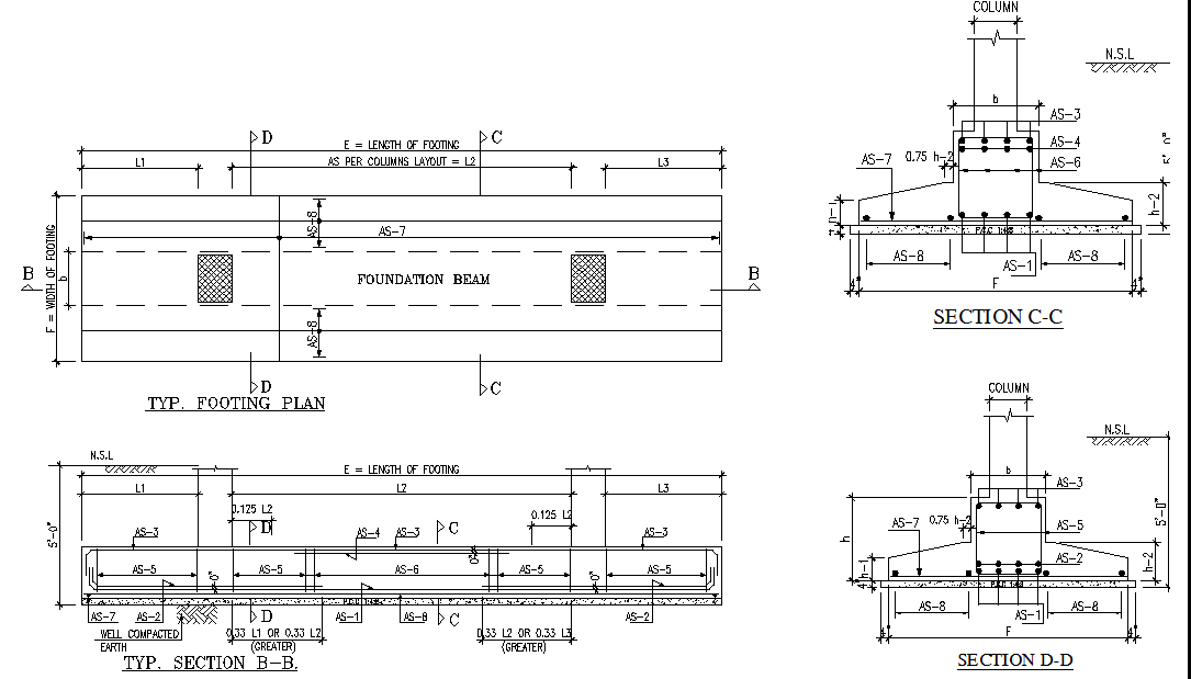
The reinforcement in center part is not like slab reinforcement. The reinforcement provided is similar to beam reinforcement. I am attaching reinforcement detail of this type of footing.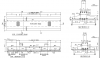
-
Combined Beam Footing Modeling In Safe
Waqas Haider replied to Waqas Haider's topic in Software Issues
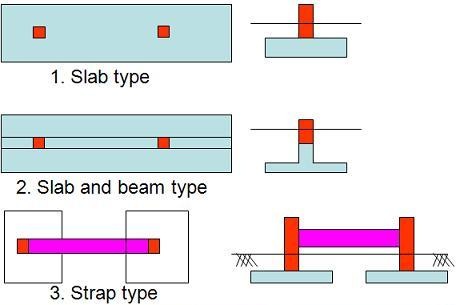
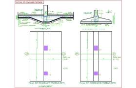
In first picture, my concern is for 2nd one labelled as SLAB AND BEAM TYPE FOOTING. Same is shown in in other two pictures. Slab and beam type or combined beam footings. I am attaching 3dview to have idea what exactly footing i m saying. Regarding Manual calculations, i have no problem for it. I have prepared my own excel sheets. But i m amazed if I have assumed correct behavior of footing components or not.The behavior I assume, goes like this 1) 1st of all, find out plastic centroid of all loads. 2) Then either try to position centroid of footing at plastic centroid or cater this extra moment too produced due to this eccentricity. 3) Then calculate bearing pressure distribution under footing. It may be uniform, it may be trapezoidal. 4) Now Slab will act as Cantilever at both ends of slab (in same manner as a single footing bend in both directions.) But in this case, slab will bend just in direction perpendicular to beam provided, because beam will act as continuous support for slab in direction parallel to beam (Just similar to wall footing). So footing is designed just for this bending. in other direction, parallel to beam, just provided minimum steel. 5) Now all pressure under footing will ultimately transfer to beam provided, and this load will act as line load at beam. Now beam is designed for this load assuming points, where columns are present, as supported. In short this whole footing and beam is designed as INVERTED both side cantilever slab resting at beam which is further supported by columns and the load acting on slab is area load equal to pressure of soil under footing. But This all is manual procedure. Kindly confirm it if I assume any thing wrong. More over, i want to check my same model in SAFE for verification. Also provide me with your sheet Waseem bhai so that I may take help of it.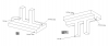
-
Combined Beam Footing Modeling In Safe
Waqas Haider replied to Waqas Haider's topic in Software Issues
Umer bhai i want to model such type of footing as i have shown in the figures attached.
-
Regarding LAP splices, In case of OMRF, IMRF, lap splices are provided just above the column beam connection because, in OMRF and IMRF, lateral forces are not much severe and there is not much problem of reversal of forces. So we can provide lap just at ends of column. But in case of SMRF, since lateral forces are severe in SDCs/sesmic zones hence reversal of stresses occur in building frames and when building will vibrate, this stress reversal will be more at column ends as compared to column center height. So in SMRF we dont provide splice at ends but in centre height. see ACI 21.6.3.2 and R21.6.3.2..... But i m confused regarding one thing, why dont we provide lap splice in OMRF and IMRF at center height while we provide in case of SMRF. Although in OMRF, IMRF and SMRF lap splice lengths are tension lap splice lengths of class B (if less than double excess reinforcement) (reference ACI 12.15), hence lap length in IMRF, OMRf, SMRF is same. then why cant we provide at mid height in case of OMRF, IMRF and we can provide in SMRF. And these locations can be omitted and changed in structure of seismic zones. Why you need to omit splice length? if your bar length are needing splice, u cant avoid it. And regarding change location of structure, wait for seniors to ans. upto my knowledge, regarding lap splice lengths, we cant change it. What can we do is , staggering of splices. Read 12.15 and there you will find Mechanical and Weld splices too. I have not read details of it yet. May be these types of splices can be used at other locations.
-
Thank you very much Sir Waseem. Kindly suggest some good book on FEM which you know and is available on net preferably.
-
If we have designed a frame assuming higher SDC than real, it means we have to provide now moment frame of higher ductility than required and hence we will reduce design forces by using higher R value than required keeping in mind the fact that now structure has higher level of dissipation. But about what advantage code is saying? More over why some one will wish to design for higher toughness in lower SDC?
-
Assalam o alaikum, Kindly clarify me the following wording from R21.1.1 Thanx.
-
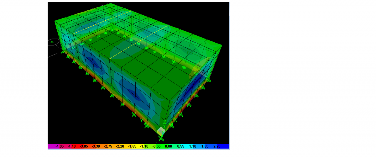
I want to get real moment forces in shells too. For the time being, positive moments are less and negative are more because of the reason that etabs has modelled slab-wall connection as monolithic. But when this connection will be released for moments, positive moments in slab and wall will increase. I want to model this in such way. Thanx.
- 5 replies
-
- 1
-
-
- simply supported shell
- slab edge release
- (and 2 more)
-
Assalam o alaikum, I am to model a basement in ETABS. Basement has 4 side walls and a slab at top. If I model slab as it as at top of walls, it behaves as partially fix support and produces moment at connections between slab and walls. But i want to release this moment.I want my slab to behave as Simply Supported where it connects wall and as monolithic where slab connects with beam and also I want my walls acting as Propped Cantilevers instead of both ends fixed. Also suggest me how to provide same connection in real by detailing of reinforcement. Jazak Allah. Thanks.
- 5 replies
-
- 1
-
-
- simply supported shell
- slab edge release
- (and 2 more)
-
Development Length Of Standard Hooks
Waqas Haider replied to Waqas Haider's topic in Concrete Design
Thank you very much bhai for you response.- 11 replies
-
- 1
-
-
- development length
- standard hooks
- (and 1 more)
-
Thank you very much bhai.
- 2 replies
-
- 1
-
-
- 12.10.1
- development length
- (and 1 more)
-
Assalam o alaikum, I m getting confuse in wording of ACI 12.10.1 under main heading of 12.10 (Development of Flexural Reinforcement), which says "Development of tension reinforcement by bending across the web to be anchored or made continuous with reinforcement on the opposite face of member shall be permitted." What does it want to say, exactly?
-
At that time I was unaware of the exact term I wanted to ask. I wanted to ask development Length of standard hook ldh because my Boss in office used to say that Provide atleast 12" dimension of column where there is beam is discontinuous. But he never told reason. Now i have known that this is the requirement for development of standard hook according to ACI-318 12.5.2 i.e. if we use #4 bars as main reinforcement, fy = 60ksi, fc' = 3ksi, the straight development length of hook, i.e. ldh will come out to be 10.95 inch beyond section of maximum stress (in case of discontinuous beam this section is face of column). So we cant provide 9" dimension of column parallel to reinforcement. Even still, 12" will not be enough and we will have to apply reduction factors to adjust this ldh in 12" column. But less than 12" column is very hard to adjust for normal conditions. Now my other question regarding this is, In masonry structures, Our beams act as simply supported beams. So Ends of beams are having zero moment and hence zero flexural stress. So we dont need to provide any ldh there. All we need to provide minimum reinforcement at end sections of beams. If what am I saying is right, how should i terminate my bars there??
-
Development Length Of Standard Hooks
Waqas Haider replied to Waqas Haider's topic in Concrete Design
PCA Commentry over 12.2.5 is Now i am confused regarding why this is not allowed? Because in those zones we design for reserve strength beyond yield too?? -
Assalam o alaikum, In Etabs, How to interperate Shell stresses/Forces. I highlighted M22 Force and i got max value as 2.61 in kip-ft units and minimum as -5.112 in Kip-ft units. What i found from the link http://docs.csiamerica.com/help-files/etabs/Menus/Display/Show_Member_Force_and_Stress_Diagrams/Shell_Forces_Stresses_Form.htm that M22: Direct moment per unit length acting at the mid-surface of the element on the positive and negative 2 faces about the 1-axis. Does it mean -5.112 Kip-ft/ft and is M22 the moment for which i am to calculate vertical steel. Kindly suggest me the value of Mu for which i am to design reinforcement. I have also attached Picture.

- 6 replies
-
- 1
-
-
- shell
- shell stresses
- (and 2 more)
-
Baz bhai, I was studying your article and since, many of terms are used in this article about which i am unaware. And i am also studying a document regarding behavior of diaphragms. I am attaching the same document. I will keep asking about other terms and confusions but for the time being kindly clarify my this confusion. You have mentioned the term SPAN-TO-DEPTH ratio. You have clarified about depth i.e. length parallel to load direction. What do you mean by SPAN?? Is it perpendicular length to Lateral loads?? If yes then it means the same slab can behave as rigid diaphragm in one direction lateral force and non rigid diaphragm in other direction lateral force according to your this statement "the slab with span-to-depth (depth is length of slab in direction of lateral loads) ratio of less than 3 and without horizontal irregularity can be treated as rigid diaphragm."??? diaphragm Design.PDF