.jpg.c0f3ad0ef57922aceb6ddba3017280bc.jpg)
Waqas Haider
-
Posts
190 -
Joined
-
Last visited
-
Days Won
17
Content Type
Profiles
Forums
Events
Everything posted by Waqas Haider
-
.thumb.jpg.700916fbc7ead330085e15745d0270bd.jpg) Assalam o alaikum, Dear seniors, I am to design a two story frame structure in Seismic zone 3. UBC tells me about two SPECIAL SEISMIC LOAD COMBINATIONS. For Zone 1, 2 A, 2B I use ASD load combinations for footing stability design i.e. bearing pressure check, uplift check, sliding check and over turning check. But for zone 3 should i include this special seismic load combinations for footing design also?? Section 1612.4 tells, for both ASD and LRFD the following special load combos should be used 1.2D + f1L + 1.0Em and 0.9D + 1.0 Em...................... for both ASD nd LRFD same combination?? I am very much confused and need urgent reply... Jazak Allah...
Assalam o alaikum, Dear seniors, I am to design a two story frame structure in Seismic zone 3. UBC tells me about two SPECIAL SEISMIC LOAD COMBINATIONS. For Zone 1, 2 A, 2B I use ASD load combinations for footing stability design i.e. bearing pressure check, uplift check, sliding check and over turning check. But for zone 3 should i include this special seismic load combinations for footing design also?? Section 1612.4 tells, for both ASD and LRFD the following special load combos should be used 1.2D + f1L + 1.0Em and 0.9D + 1.0 Em...................... for both ASD nd LRFD same combination?? I am very much confused and need urgent reply... Jazak Allah... -
Assalam o alaikum, Dear seniors, I am to design a two story frame structure in Seismic zone 3. UBC tells me about two SPECIAL SEISMIC LOAD COMBINATIONS. For Zone 1, 2 A, 2B I use ASD load combinations for footing stability design i.e. bearing pressure check, uplift check, sliding check and over turning check. But for zone 3 should i include this special seismic load combinations for footing design also?? Section 1612.4 tells, for both ASD and LRFD the following special load combos should be used 1.2D + f1L + 1.0Em and 0.9D + 1.0 Em...................... for both ASD nd LRFD same combination?? I am very much confused and need urgent reply... Jazak Allah...
-
Assalam o alaikum, Can any one provide me with some clause, code or literature where i can find exact minimum end bearing of beam required in frame as well as masonry structures?? It is 9" or 12"? Jazak Allah...
-
Spring Support- Modulus Of Subgrade Reaction
Waqas Haider replied to Waqar Saleem's topic in Foundation Design
Waqar Saleem Bhai, I would suggest u read this document. last month i was also very much confused regarding this spring option in softwares. This document helped me much. I wil upload other documents too when i will find them. But this is good... In last topic of this document, u will get to know how to calculate stiffness of soil spring using bearing capacity... Correlation_BC_and_K.pdf- 9 replies
-
- 4
-

-
- spring support
- Modulus of subgrade reaction
- (and 2 more)
-
Assalam o alaikum seniors, I am searching for some design example of TIE BEAM DESIGN.... I am having sap reactions of all the columns.. I need detail of manual design of tie beam. Or info how to design it. I also want to design it for differential settlement of columns and for lateral loads also... How shud i take these loads in my design??? If i design this beam in sap2000, i apply gravity load and support settelemnt of 25 mm at one end of beam and design it, will it be OK? Shud i take soil reaction from bottom or shud i neglect it? Jazak Allah...
-
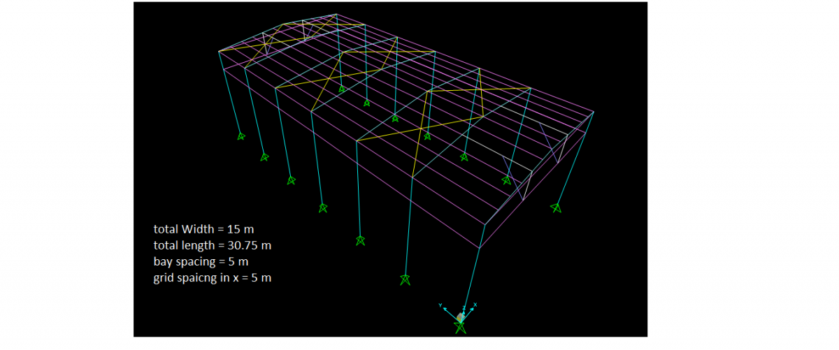
Bhai why dont this will act as resisting member? major axis of column of this this portal bracing, shown in red in figure, is perpendicular to wind from y axis. so i think it will resist load of wind. Roof bracing will just act as diaphragm. This all what i am thinking. The picture of my model is also attached here.....

-
Assalam o alaikum.. I am having a model of steel shed in sap. I m to model a portal frame bracing in this shed as shown in attached figure. but far that i am to model column of main frame and column of portal bracing at same grid. What should i do??

-
Tension Only Bracing Cables In Sap2000
Waqas Haider replied to Waqas Haider's topic in Software Issues
Cant we do this in sap2000? My model is in sap. -
Thanx for ur reply bhai.. infact i modeled a plane portal fame in sap and for self load it bends. but i am having some value of rotation at the joint between beam and column... i.r. R1=0.003 this rotation is with respect to global axis or it is relative rotation of column and beam? Because in rigid connection there is no relative rotation of members. when i simply connect beam and member in sap, is it a rigid connection or partially fixed?
-
Assalam o alaikum.... how can we assign tension only cable bracing in sap2000? When i assign cross bracing in roof, both of cables start taking load..... i want only cable bracing in tension must take load.
-
Assalam o alaikum... how can we assign rigid connection to a simple frame consisting of two vertical columns and one Horizontal beam in sap2000.....??
-
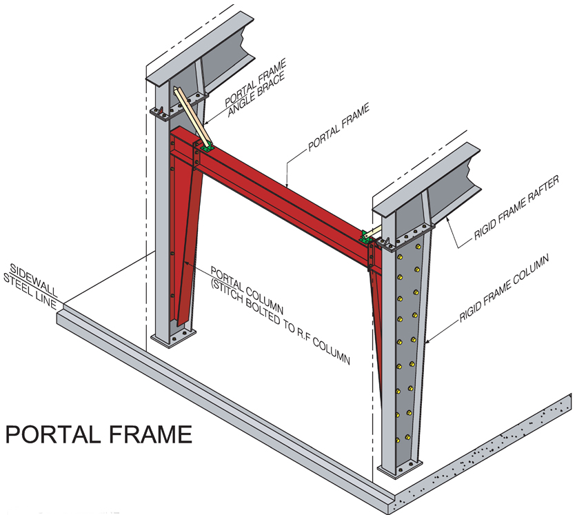
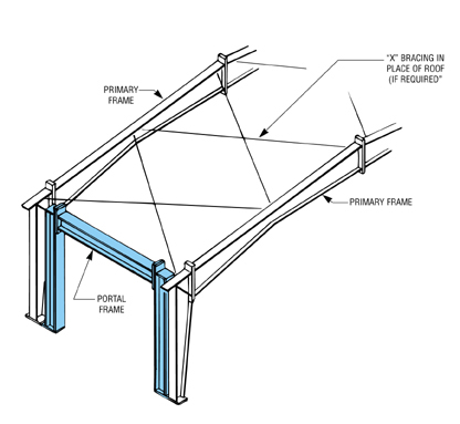
Assalam o alaikum seniors.... I am to design a steel shed where i can not provide diagonal bracing in side walls because of space restrictions. I am to provide a Portal frame bracing as shown in figure. Can any one provide me with some study material on how to design this portal frame bracing? Jazak Allah..

-
Steel Column Base Plate Modelling In Sap
Waqas Haider replied to Waqas Haider's topic in Software Issues
Ni bhai... At bottom of steel column,, there is not footing... there is a concrete pedestal of 8 ft height.. and footing is below this pedestal.. so the reactions obtained from SAP, will not be at top of footing.. it will be at top of pedestal... and due to this reason, i want to transfer my reactions.............. i know how to transfer loads along with accompanying moments manually i.e. by multiplying each reaction with height of pedestal... but can i model this pedestal into sap along with steel column?? if yes, then how to model it properly? -
Steel Column Base Plate Modelling In Sap
Waqas Haider replied to Waqas Haider's topic in Software Issues
Thank you Waseem bhai for ur reply... i am infact confuse that i have two option to design isolated footing.... 1st way is that i model steel column with hinged connection at base. the note down its reactions in SAP and do manual calculations for the design of footing and pedestal... the reactions, noted in SAP would be imagined at the top of pedestal of footing.. then i will have to transfer this reactions from top of pedestal at the top of footing along with the moments produced due to these reactions at the top of footing by multiplying these reactions with the height of pedestal. the i can use these Fx, Fy, Fz reactions along with moments Mx, My, produced due to this transfer because reactions are acting at top of pedestal and i have transfered this to top of footing... now i can design my footing for this Fx, Fy, Fz, Mx, My either manual or using safe........ 2nd way i have is, I can model the very same pedestal at bottom of steel column and fix the base of pedestal... in this way i can get automatically, transferred moments (Which i was transferring myself by Fx*H or Fy*H) at the top of footing... But the results of both of them are not matching. And I also cant understand what type of conenction i must provide at the connection of steel column to pedestal in SAP...... Which of my way is OK out of 1 and 2? -
Respected seniors, It is my 1st post. I have got help from this forum many times but posting 1st time.. i am a junior structural engineer.. i am to model a steel column resting at 8 ft concrete pedestal of isolated foundation... The base of steel column is attached resting at pedestal with the help of a hinged type base plate... but i am confused what type of constraint i shud provide at the connection of steel column base at pedestal.... i even dont know exactly what a constraint is... i am to design foundations of column. so kindly let me know how to model it properly and accurately...