
.jpg.c0f3ad0ef57922aceb6ddba3017280bc.jpg)
Waqas Haider
-
Posts
190 -
Joined
-
Last visited
-
Days Won
17
Content Type
Profiles
Forums
Events
Everything posted by Waqas Haider
-
.thumb.jpg.700916fbc7ead330085e15745d0270bd.jpg)
Confined Masonry Guidelines Pakistan
Waqas Haider replied to UmarMakhzumi's topic in Journal/ Articles/ Tutorials
Thanks a lot. Keep it up. You are serving engineering community a lot... -
For design of beam footing, either you cand consult PRC 1 by Z A SIDDIQUE or search the forum. There are other discussions also.
-
My opinion is that, beam foundation is mostly suited when loads coming from super structure are excessive and causing punching shear in footing. So instead of increaisg depth of whole footing, we provide tapered footing or we go for beam footing. But since in case of wall, there is no case of punching shear. And only one way shear exists. Which is nearly same either you provide beam or not. Again if u r having excessive one way shear u can again go for beam footing or tapered footing. again if u think tapering will cost more go for localized thickneing by providing beam. More over, providing beam also causes increment in rigitiy of footing. I will personally provide strap footing.
-
Assalam o alaikum. Why dont we model masonary wall in etabs while modeling frame? Walls are there with their stiffness participation by reducimg displacements in an earthquack. Is it because we consider walls will fall when seismic force will act on walls perpendicular to plan of walls? More over one of my friend told me that now a days practice of construction in islamabad, quetta and kashmir , houses are built with masorany walls along with columns. The frame provided is designed for lower seismic zone than original and for lower ductility. My question is does it act as dual system? Means walls are considered to resist lateral forces and the frame ( in which beam is not designed to take slab load) is provided just to have some extra stiffness.... what exact concept is used behind such design, if any one is familiar with?
-
The dimension of column is very big. R u sure? What is the project exactly? More over why r u facing problem in design of footing? It must be same and dimension of column should be taken at bottom of column.
-
@UmarMakhzumi So for model 2, frame only, instead of playing with modifiers, can we go to reduce effective mass multiplier to 0.25 as Ilyas said?
-
Does vertical distribution depends on time period? It must depends on weight participation and stiffness of floors.
- 29 replies
-
- 1
-

-
- t-computed less than ta
- base shear time period
- (and 3 more)
-
As umer makhzumi bhai said, for seperate model without shear walls, the approach told by ilyas should be ok. But I doubt the interaction with shear walls is not taken into account if we design frame for 25% shear separately. Kindly share you solution how to cater it in etabs.
-
If you share your found solution with this forum it would be of great help for others. Thanks in advance.
-
Is it from some document? Kindly give reference. I would like to study more about it. thanks.
- 23 replies
-
- 1
-
-
- wind story drift limits ubc
- drift
- (and 1 more)
-
Kindly explain for what purpose? Because for seismic drift, @Rana Waseem sir has explained only seismic CASE should be used. instead of Ex or Ey with any combination.
- 23 replies
-
- 1
-
-
- wind story drift limits ubc
- drift
- (and 1 more)
-
I think for single column or single beam, This statement seems true but for a frame in ETABS, relative difference between stiffness of column and beam must be provided so in any case 50% difference between stiffness of both beam and column must be provided. Am I right? I have few questions here. 1) Does ETABS design beam for positive region as T-beam or Rectangular beam? Mean does it takes into account monolithic behavior of beam with slab and make part of slab acting as flanges or not? 2) If it only design as rectangular beam, why it has algorithm of T-beam design in its manual? 3) If it design as T-beam also depending on neutral axis depth, we will have to provide 0.35 modifier for beams because here T beam is being taken as T beam in positive region so its stiffness must be les than 50% than column so we will have to use 0.35I for beams.
-
If you are having a geotechnical report with you, there must be clearly stated value of spring constant with the name Modulus of Subgrade Reaction. Incase soil investigation have not been done on site for any reasons, you can use a tentative value for k by following relation. k = 3 x qa x 12 (in FPS in k/ft3) k = 3 x qa x 40 (in SI in KN/m3) where qa = allowable bearing capacity. and 3 is Factor of safety applied on soil while determining bearing capacity of soil. For the reference of this formula, please read the attached document. Correlation_BC_and_K.pdf
- 10 replies
-
- 2
-
-

-
- raft
- raft etabs
- (and 1 more)
-
Great..!!! I m only familiar with Engr Junaid because he is my class fellow, with Umar Makhzumi Bhai, and With Waqar Saleem Brother. Today I came to know what is full form of BAZ And he has changed his looks also. By the way, I used to think Engr Uzair Sir quite younger but he is quite senior to us. Mostly people after getting senior does not use social media forums much.. especially for responding people.. Really nice to know the members. This forum is really great.!!
-
You must export combos related to all loads i.e. gravity and lateral loads because ultimately effects due to all the loads is going to be transferred to foundation. Designing foundation only for gravity loading is not correct approach. But remember, since mostly bearing capacity provided by Geotechnical consultant is safe bearing capacity instead of ultimate bearing capacity (safe bearing capacity means full factor of safety has been applied to bearing capacity as we do in ASD approach). Hence if we use this bearing capacity for design of foundations, loading combos of ASD or unfactored loading combos must be used. UBC and IBC provides these laod combos and footing must be designed for all this loading combos instead of autogenerated loading combos of ETABS which are factored. Either define these loading combos in etabs and export to safe or directly define then in safe. Increase of bearing capacity upto 33% is not allowed in all the cases. It can only be used where in loading combos having two or more variable/Transient loads togather, we have not reduced the intensity of transient loads. If we have reduced these loads by 0.75 factor then bearing capacity can not be increased by 33%. Basically it is not the case with bearing capacity only. Any strength determined by using ASD approach (i.e. full factor of safety applied on strength of member, ) can be increased by this approach but only if in loading combos transient loads have not been reduced. UBC and IBC proposes two types of loading combos for ASD. in first type of combos you may find for example a combo D+L+W and in 2nd type you can find the same combo as D+0.75L+0.75W. if you use first type of combo you can increase by 33% and if u r using 2nd type of combo, note that the loads have been reduced by 1/1.33 = 0.75 times instead of increasing strength. so same factor of 1.33 has been applied on load side so in this case no increase can be made in strength. For a detailed study refer to following document. 1-3rd stress increase AISC.pdf
-
Kindly mention names of members as we are unfamiliar with faces. Thanks..

-
Can you please provide the complete document? thanks.
-
Slab Reinforcement with Inverted Beams.
Waqas Haider replied to The Architect's topic in General Discussion
In regular non inverted beams, the negative steel of slab rests on the upper portion of beam which is in compression and hence fully available for end bearing load of slab. But in inverted beams, this negative steel rests on the lower portion of beam which is in tension (in middle span) and hence will be having flexural cracks (though up to minor crack widths), I m amazed if this cracking affects the bearing strength in any way.- 2 replies
-
- 1
-
-
- slab
- reinforcement
- (and 2 more)
-
Relation between Temprature reinforcement and grade of steel
Waqas Haider replied to Waqas Haider's topic in Concrete Design
Kindly give your value able comment over this also. thanks. Is proposal of temp. steel by ACI based on the thing that this temp steel may have to bear temp stresses upto yielding and higher steel strength can support more portion of concrete in temp stresses so requiring less steel and vice versa? If this steel ratio is quite higher as compared to yielding of steel then why cant we have same ratio for both of grade? -
Assalam o alaikum dear fellows, Why we need more temperature steel ratio for lesser grade of steel as shown by following relation? For Fy = 40 ksi As(min) = 0.002bh For Fy = 60 ksi As(min) = 0.0018bh Moreover, According to 7.12.1.2, it says 7.12.1.2 — Where shrinkage and temperature movements are significantly restrained, the requirements of 8.2.4 and 9.2.3 shall be considered. And in its commentary it says R7.12.1.2 — The area of shrinkage and temperature reinforcement required by 7.12.2.1 has been satisfactory where shrinkage and temperature movements are permitted to occur. Where structural walls or columns provide significant restraint to shrinkage and temperature movements, the restrain of volume changes causes tension in slabs, as well as displacements, shear forces, and flexural moments in columns or walls. In these cases, it may be necessary to increase the amount of slab reinforcement required by 7.12.2.1 due to the shrinkage and thermal effects in both principal directions (see References 7.7 and 7.16). Kindly tell how to increase this amount? Thanx.
-
Choice between rectangular and Tee Beams
Waqas Haider replied to Waqas Haider's topic in Concrete Design
Mean if I provide beam of 12" x 24" in ETABS with slab on both sides. It will never be designed as a rectangular beam of 12" x 24" for positive moments as we consider in example problems while studying design of rectangular beams. Either it will be designed as a beam of section b x 24" (where b = effective flange width of T beam which is greater than width of web) if N.A. lies with in flange OR it will be designed as a Tee beam for positive moment if N.A. lies outside of flange. am I right? Is this the reason we always get reduced steel in ETABS in beams modelled with slab as compared to manual calculations. (Also I assume that connection with slab causes to reduce bending of beam as compared to isolated beam and hence reduces steel.) Kindly verify. Thanks. -
Assalam o alaikum. If we model a rectangular beam in ETABS with slab on both sides of beam, will it be designed as a TEE beam or rectangular beam? More over in real structures and manual calculations, Nearly every beam is cast monolithically so should all the beams designed as TEE beam? If yes then what is practical example of rectangular beam carrying slab load?
-
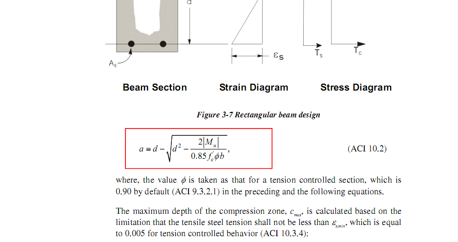
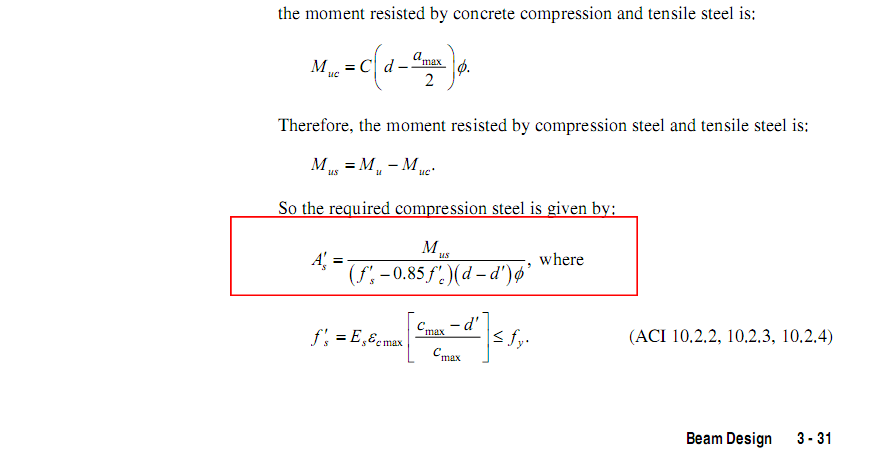
Assalam o alaikum, I was reading ETABS concrete frame design manual ACI 318-08. In beam design section, it gives two formulae which I am unable to find in books. One formula for stress block depth and one formula for negative steel calculation. I have highlighted the formulae in below images. The manual design using these formulae and conventional formulae gives the same result. But kindly guide me from where I can get derivation of these formulae or theory behind this.
-
@Ahsan Kazmi right click the column and go to flexure details There you can find the design combo Check if it includes lateral loads It will also tell you the design moments for this reinforcement
-
Thanks Uzair.
