.jpg.c0f3ad0ef57922aceb6ddba3017280bc.jpg)
Waqas Haider
-
Posts
190 -
Joined
-
Last visited
-
Days Won
17
Content Type
Profiles
Forums
Events
Everything posted by Waqas Haider
-
assalam o alaikum, Dear Seniors, Kindly clarify what is the difference between MAT and FOOTING option in SAFE while defining slab property. Thanks.
-
Kindly clarify details of section? What diameter and thickness you are using for pipe sections? And sheet thickness you mentioned is sheet of billboard? What exactly structural system you are using?
-
Assalam o alaikum, What are load cases for which i need to check my deflection. ACI table 9.5 ( b ) there need to check two types of deflections. i) Immediate deflection due to live load ii) Total deflection [which is sum of long term deflection due to sustained loads [sustained load means majorly dead load and some portion of minimum live load which is permanently applied] and immediate deflection due to live load) And long term deflection can be calculated as immediate deflection due to sustained loads (sustained load means majorly dead load and some portion of minimum live load which is permanently applied) multiplied by 2. So equation goes some what like this i) for immediate deflection, Deflection = immediate due to live ii) For Total Deflection Total Deflection = immediate + long term where immediate deflection due to Live Long term deflection = 2 x Immediate deflection due to dead 2 is taken for simplicity in case of five years so Total deflection = immediate deflection due to Live + 2 x immediate deflection due to sustained load (dead majorly) Kindly varify.
-
Assalam o alaikum. According to 21.5.1, width of beams must satisfy the following 1. Clear span ln ≥ 4 effective depth General 2•Width to depth ratio bw/h ≥ 0.3 3.Width bw ≥ 10 in. It means, i can provide 10 inch thickness in zone 4, if it is satisfying above 3 clauses. Is there further limit?
-
i have not yet studied about it but for the time being i m also facing a problem regarding deflection. What i suggest u for ur problems regardign software is, ETABS has its manuals in which CSI has shown how etab works and do background calculations you can find these manuals in the directory where etabs is installed. I will post back if i will find answer.
-
.thumb.jpg.700916fbc7ead330085e15745d0270bd.jpg)
Relative Stiffness Of Beams And Columns
Waqas Haider replied to Hasan Tariq's topic in General Discussion
in case of fixed ended beam, there is no rotation at supports. but when a beam is modeled with its supports on column, then there is rotation at ends of beam because of bending of columns. So this support is not fixed. And not simply supported because beam ends are not fully allowed to rotate as in case if beam is resting on masonry walls. If beam is continue then for approximation u can use moment coefficient method. Other wise u can use wl2/11 or wl2/12 for end and midspan moments as conservative design. You can also model this frame in etabs. -
Assalam o alaikum. I have two questions. 1) Since I have provided my tie beams at plinth level so in my case , do tie beams, plinth beams, grade beams, all mean same? 2) ACI 21.12.3 deals with grade beams and Slab on grades. ACI 12.12.3.2 says "Closed ties shall be provided over the length of beam spaced at a maximum of one half the smallest orthogonal cross sectional dimensions of the beam or 12 inch, which ever is lesser." Moreover ACI 21.12.3.3 says "grade beams and beams that are part of a mat foundation that is subjected to the flexure from the columns that are part of seismic force resisting system shall have reinforcing details confirming to ACI 21.5 for flexure members of special moment frames. But ACI 21.5 says hoops shall be provided at a spacing not more than d/4. Does it mean that restriction of 21.5 only applies to tie beams if tie beams are suffering from flexural effects? And kindly explain what "flexure from the columns" means?
-
Maximum Allowed Steel Ratios In Slabs And Footings
Waqas Haider replied to Waqas Haider's topic in Concrete Design
Thank You so much For such a detailed Answer. Kindly also explain me about Maximum Allowed reinforcement in slabs/footings.- 7 replies
-
- 1
-

-
- maximum reinforcement
- maximum steel ratio
- (and 2 more)
-
Assalam o alaikum, Can any one tell me what is maximum limit of positive and negative steel ratios in slabs and footings? ACI code is giving me minimum limit in terms of percentage of gross area i.e. 0.002.b.h or 0.0018.b.h. but it reports maximum allowed reinforcement in terms of net tensile strain in tension reinforcement. Kindly explain what value it means in terms of gross area for maximum allowed steel ratio to avoid over-stressing of slabs and footings?
-
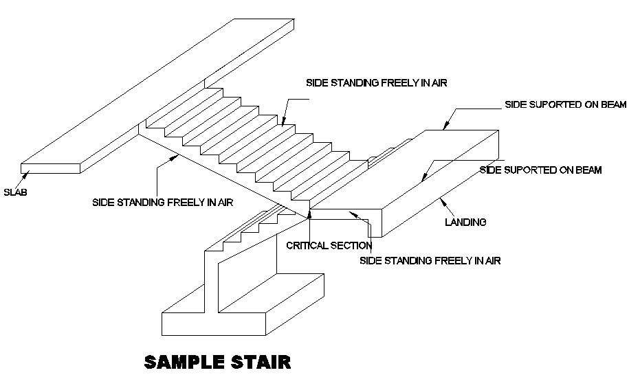
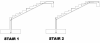
Assalam o alaikum... I have attached two images. One image titled STAIR TYPES and one image as titles SAMPLE STAIR. STAIR TYPES image contain two drawings. Two different type of detailing for reinforcement. I am confused which out of two should be used and what basically structural difference is there? I think in STAIR 1 (see image attached) there is no moment capacity at connections of flight and landing etc whereas in STAIR 2(see image attached) there is moment resisting capacity at connections of flight and landing etc ... SAMPLE STAIR image contain question problem. I am having this type of stair in my building where landing is supported at two intersecting sides and other two sides are unsupported and standing in air or connecting with flight. What type of reinforcement would be suitable for this case? Thanks.
-
Need Confirmation About Modelling In Safe
Waqas Haider replied to Waqas Haider's topic in Software Issues
Thank you so much Junaid Bhai for you detailed answer... -
I am really thankful to members of this forum for their nice and sincere work. This forum is really helping students like me with variety of knowledge, concepts and practicality.
-
Deduction Of Overburden From Bearing Capacity
Waqas Haider replied to EngrUzair's topic in Foundation Design
When ever we say Allowable bearing capacity, It can be either Gross allowable bearing capacity or net allowable bearing capacity. And it is the most important thing to decide when to add over burden, when to subtract and when not to. More over keep this equation before you for equilibrium q(all.gross) > P/A +Y.Df where q(all.gross) = gross bearing capacity Y.Df = Backfill load P/A = Applied pressure q(all.net) = q(all.gross)-Y.df = (P/A +Y.Df) - Y.Df hence for equilibrium q(all.net) > P/A where q(all.net) = net allowable bearing capacity Y.Df = Backfill load P/A = Applied pressure So gross bearing capacity is capacity available to bear pressure of existing soil as well as applied loads and net bearing capacity is capacity available to bear just applied pressures because pressure caused by existing soil has already been deducted. Case when NOT to deduct over burden Lets say in my geotechnical report i have been provided by NET bearing capacity of 1 tsf at a depth of 5 ft. Now it means at 5 ft depth, soil is capable to bear pressure of 1 tsf IN EXCESS of existing soil. Because it is NET allowable bearing pressure and pressure of existing soil has already been subtracted/balanced from bearing capacity. Now only extra available bearing capacity is reported as net. The soil can bear 1 tsf of EXTERNAL/APPLIED pressure which includes load of above structure as well as load of footing. Load of footing is also external and applied. In this case, you need not to deduct over burden because over burden is already deducted and you are provided with NET bearing capacity. But If you have bearing capacity at 5 ft depth but in return you have plan to backfill upto 7 ft, then obviously extra 2 ft soil is applied pressure. which you need to either add in applied pressure or you should deduct it from the bearing capacity. Case when to deduct over burden But if my geotech report says me that at 5 ft depth, i have 1.25 tsf GROSS allowable bearing capacity. Now it means my soil is capable to bear 1.25 tsf pressure including pressure caused by existing soil. Because it is gross allowable bearing pressure and i have not subtracted pressure of existing soil. The soil can bear 1.25 tsf of total pressure which includes EXTERNAL/APPLIED pressure caused by load of above structure including load of footing, and pressure caused by existing soil . In this case, for the sake of sizing of footing, you need to to deduct weight of over burden soil so that so may find out net bearing capacity available to resist applied load of structure and footing. Note that, after deducting the pressure caused by existing soil i.e. Y.Df = 110*5 = 550 psf = 0.25 tsf, we again get the same 1tsf bearing capacity available for external/applied loads. Case when to ADD over burden Now Let say you are given with any of capacity. Let say Net allowable capacity of 1tsf at 5 ft depth. But you know that you are not going to backfill the foundation (in case of basement etc), then NOT ONLY this 1 tsf is available for applied pressure but also that 0.25tsf available which was going to be consumed by existing soil backfill. Now you can add this 0.25tsf to your net bearing capacity to get bearing capacity, available for external loads and you need to find out size of foundation according to this available bearing capacity. -
The document presented by Sir Umer clearly says that this stress increment should not be taken even in case of earth quack loads if 0.75 reduction factor has been already used in load combinations. More over, in sizing of footing, we go for ASD approach because bearing capacity given by geotechnical engineer is based on the concept that full factor of safety of 2-3 is applied on soil strength and no loads are increased. This is ASD methodology. So to be compatible, we also go for ASD while sizing of foundation. So in my opinion, if you are using load combinations which are carrying 0.75 reduction factor, you can not increase soil stress by 33% even not for earth quack loads. but if you are using the load combinations which are not having 0.75 reduction, then you can increase this stress as 33% but just for those cases where two or more than two transient loads are acting simultaneously.
- 16 replies
-
- 3
-
-
- foundation
- load
- (and 3 more)
-
What I have concluded after reading above posts and documents, is that 1) The 1/3d increase in stress by ASD method may be either due to i) loading rate ii) loading duration iii) some other such reason based on engineering judgement iV) And most importantly due the reason that when two transient loads (loads having tendency to vary in magnitude with respect to time e.g. live, earth quack, wind etc) act simultaneously on a structure, then one transient load acts as full value load and other structure has less probability of occurrence. So it is not fair to combine these two transient loads at their full value loads. So both of the transient loads are either allowed to reduce upto some extent (As codes specify 25% reduction in transient loads) OR corresponding stress in material is increased by 33%. (Note that 0.75 is reduction factor for transient simultaneously acting loads and reciprocal of 0.75 i.e. 1/0.75 = 1.33 i.e. increment factor of stress. ) Basic equation of equilibrium is Loads = Stress In case of simultaneously acting transient loads, either you can do 0.75*loads = stress OR Loads = stress/0.75 = 1.33*stress But keep in mind that since this stress increment is due to the fact that both transient loads can not act simultaneously at their full value so we are reducing loads or increasing stress. This stress increment has nothing to do with DEAD LOADS. So we can not reduce dead load and this factor of 0.75 is applied only to transient loads. You can find in different codes in practice two types of load combinations. Basic and Alternate. One type of load combinations include this 0.75 reduction factor in them so using these types of load combinations we can not increase stress. because reducing loads for the same reason and increasing stress for again the same reason SIMULTANEOUSLY is UNSAFE. You can go for one approach at a time. More over, Codes also say that the effect due to load combination carrying two or more transient loads with reduced values must not be less than the effect of only one (most severe) transient load acting at full value.
-
Waseem bhai Can you please upload the link/document of ASCE 7 commentry? In my version of ASCE 7-10, Commentry pages are missing. You please share so that we may download.
-
What is meant by SW waseem bhai?
- 5 replies
-
- 1
-
-
- simply supported shell
- slab edge release
- (and 2 more)
-
Seismic Hoops In Zone 4 Diameter Restriction
Waqas Haider replied to Waqas Haider's topic in Seismic Design
Is this a MUST check to perform? What If I just provide ratios obtained from ETABS and dont satisfy it? From Etabs I got much lesser required rations i.e. 2 legged #3 @ 4 inch is satisfying my etabs required ratio. But ETABS MANUAL of concrete frame design CFD-ACI-318-08, Topic 3.4.4.3 says "The column shear reinforcement requirements reported by the program are based purely on shear strength consideration. Any minimum stirrup require- ments to satisfy spacing considerations or transverse reinforcement volumetric considerations must be investigated independently of the program by the user." ACI 318-08 R21.6.4.4 says "Instead, Eq. (10-5) and (21-4) are required, with the intent that spalling of shell concrete will not result in a loss of axial load strength of the column. Equations (21-3) and (21-5) govern for large-diameter columns, and are intended to ensure adequate flexural curvature capacity in yielding regions."- 5 replies
-
- 1
-
-
- seismic hoop
- zone 4
- (and 1 more)
-
Seismic Hoops In Zone 4 Diameter Restriction
Waqas Haider replied to Waqas Haider's topic in Seismic Design
in my case column size is 12x21, And regarding calculations of my transverse reinforcement, spacing came out 4 inch max. Now according to 21.6.4.4 of ACI 318-08 I am to provide not less than giver by following two equations Ash = 0.3*s*bc*fc'/fyt*[(Ag/Ach-1)] or Ash = 0.09*s*bc*fc'/fyt in my case s = 4 inch bc = 9 inch for one direction and 18 inch for other fc' = 3ksi fyt = 40ksi Ag = 252 in2 Ach = 162 in2 So in my case For bc = 18 inch Ash = 0.9 and Ash = 0.486 So I need to provide at least 5 legs of #4 stirrup perpendicular to 21 in dimension For bc = 9 inch Ash = 0.45 and Ash = 0.243 So I need to provide at least 3 legs of #4 perpendicular to 12 inch dimension. baz bhai, am i getting it right? -
Assalam o alaikum, Is there any restriction on diameter of shear hoops in seismic zone 4? We can not provide less than 3/8 in stirrups. But for seismic zone 3,4 is there any further restriction regarding size of stirrup? My main concern is to know whether i can use 3/8 in dia stirrups hoops in zone 4 if it is satisfying spacing limits and required shear ratio? Thanks.
-
Assalam o alaikum, How much important width of column strip is in SAFE? One of my friend told me that his boss (Owner of Arif Associates Lahore) told him that width of column strip assigned in SAFE, should be minimum 1.5h+c (where h= thickness of footing/slab and c=dimention of column parallel to width of strip) and told him that it is critical width. I searched about it and in ACI detailing manual 2004, in article 2.10.10, i found " Two-way slabs without beams-Moderate seismic risk -Reinforcing steel for the fraction of Mu to be trans- ferred by moment (Eq. (13-1), AC1 318 [318M]), but not less than half the total reinforcement required for the column strip, shall be placed in the width of slab between lines 1.5 times slab or drop panel thickness on opposite faces of the column. (This width equals 3h + c2 for edge and interior col- umns or 1.5h + c2 for corner columns.) The AE shall show the reinforcing steel to be concentrated in this critical width. See Fig. 19(d) in Part C for typical detail used for locating other bars in nonseismic areas." I am confused what is link between this critical width and width of design strip in safe? What if i assign 1 ft design column strip and provide the reinforcement upto this said critical width? will it be wrong? Thanks.
-
Strap Beam In Raft For Columns Punching Shear Problem Counter
Waqas Haider replied to Yousuf Ali's topic in Foundation Design
regarding locallized thickness increment, i am very much confused. I have done this. I drew a slab of 9" thickness with column size of 24". I decided to increase thickness in critical zone upto 24" and hence my critical perimeter would be at a distance of d/2 (22.5/2 = 11.25 inch) from face of column. But i tried, for the sake of checking, for 24" square column, i just drew another slab of dimensions 2.1ft x 2.1ft. Now it does not even cross d/2 critical section but SAFE takes effective depth for 22.5 inch. I was studing SAFE MANUAL titles "SAFE KEY FEATURES AND TERMINOLOGIES" where in section 6.3, in SLAB PUNCHING SHEAR CHECK, point 2, says, "Check that each slab element in the area enclosed between the face of the column and the critical section for punching shear has the same slab property label. If this is not the case, the minimum slab thickness within the punching shear perimeter is used. " Now I m confused, SAFE should take effective depth 7.5 inch instead of 22.5 inch because i have not provided 24" till d/2. My version is 12.3.1 -
Assalam o alaikum, I am designing a concrete frame in seismic zone 4 to which I have assigned seismic design category E. I ave insufficient data for site soil so I have assumed soil type Sd. Now I m to ask that IBC 2009 1809.13 says,footings must be interconnected. Whether this requirement only for Site Classification as E,F or it is for all site classifications? Moreover this requirement means tie beams must be at footing level or Tie beams provided at plinth level also satisfies this provision? Thanks.
-
Good Engineering Consultants In Lahore
Waqas Haider replied to Waqas Haider's topic in General Discussion
I contacted with Arif Associates. Sir Arif said, he needs some one with minimum experience of 3 years so that he dont need to teach any thing. My experience is of 1.5 years. Noor Durrani is in the same street where my office H.H.Robertson is. Is Rizwan Mirza Associates for buildings? I heard it deals with poultry farms. -
In my case, Architecture has not proposed this. Lets say he is unaware of suitable finishing, what finishing should i suggest him for floor and roof for normal usage?