Saiful Islam Zaber
-
Posts
35 -
Joined
-
Last visited
Recent Profile Visitors
2796 profile views


Saiful Islam Zaber's Achievements
")
Newbie (1/14)
1
Reputation
-
Found any solution ?
-
 Saiful Islam Zaber changed their profile photo
 -
 Saiful Islam Zaber reacted to a post in a topic:
Career Guidance
Saiful Islam Zaber reacted to a post in a topic:
Career Guidance
-
It seems to me required rebar for both Negative and positive moment is wrong?
-
Saiful Islam Zaber reacted to a post in a topic:
MAXIMUM REINFORCEMENT FOR BEAM IN ETABS
-
MAXIMUM REINFORCEMENT FOR BEAM IN ETABS
Saiful Islam Zaber replied to Saiful Islam Zaber's topic in Software Issues
@BAZ @EngrJunaid @ILYAS @UmarMakhzumi @waqar saleem @Rana -
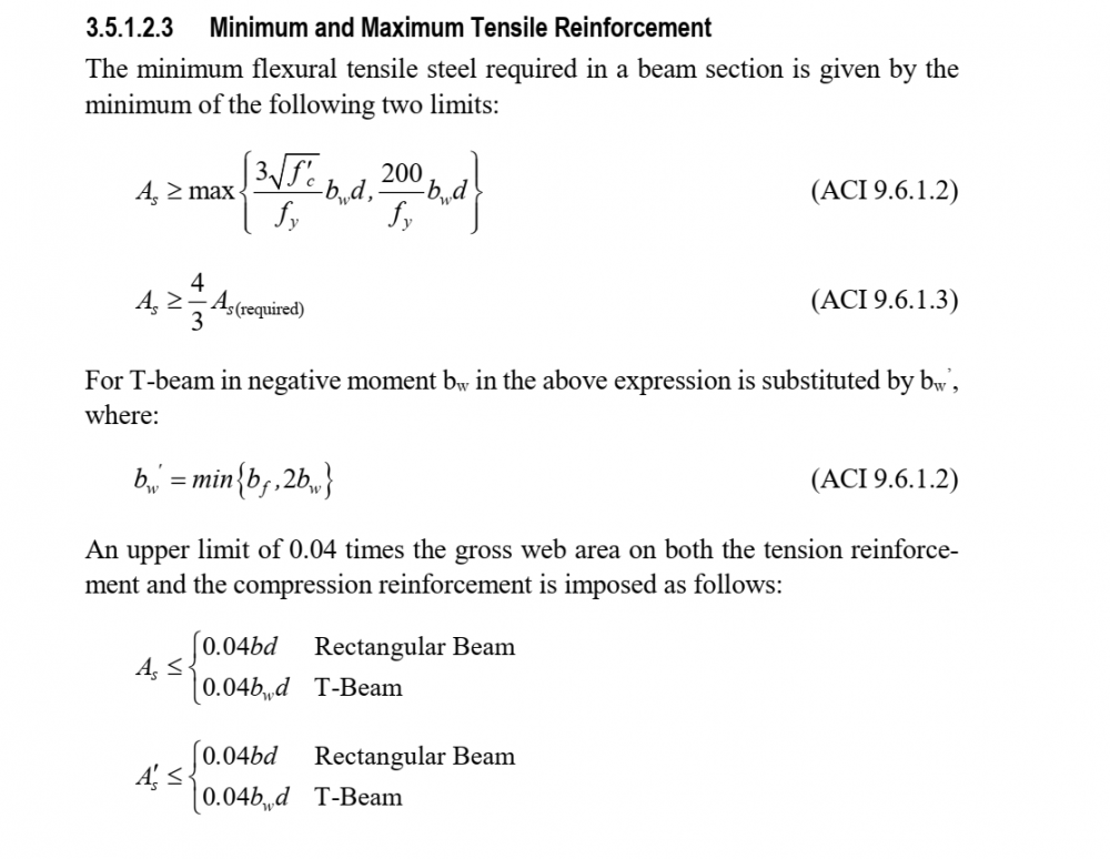
As per Etabs Manual Maximum reinforcement limit for rectangular beam is .04bd. But Couldn't find this limit in ACI Code. Please refer me to the code article.
-
Saiful Islam Zaber reacted to a post in a topic:
DOUBLY BEAM DESIGN IN ETABS
-
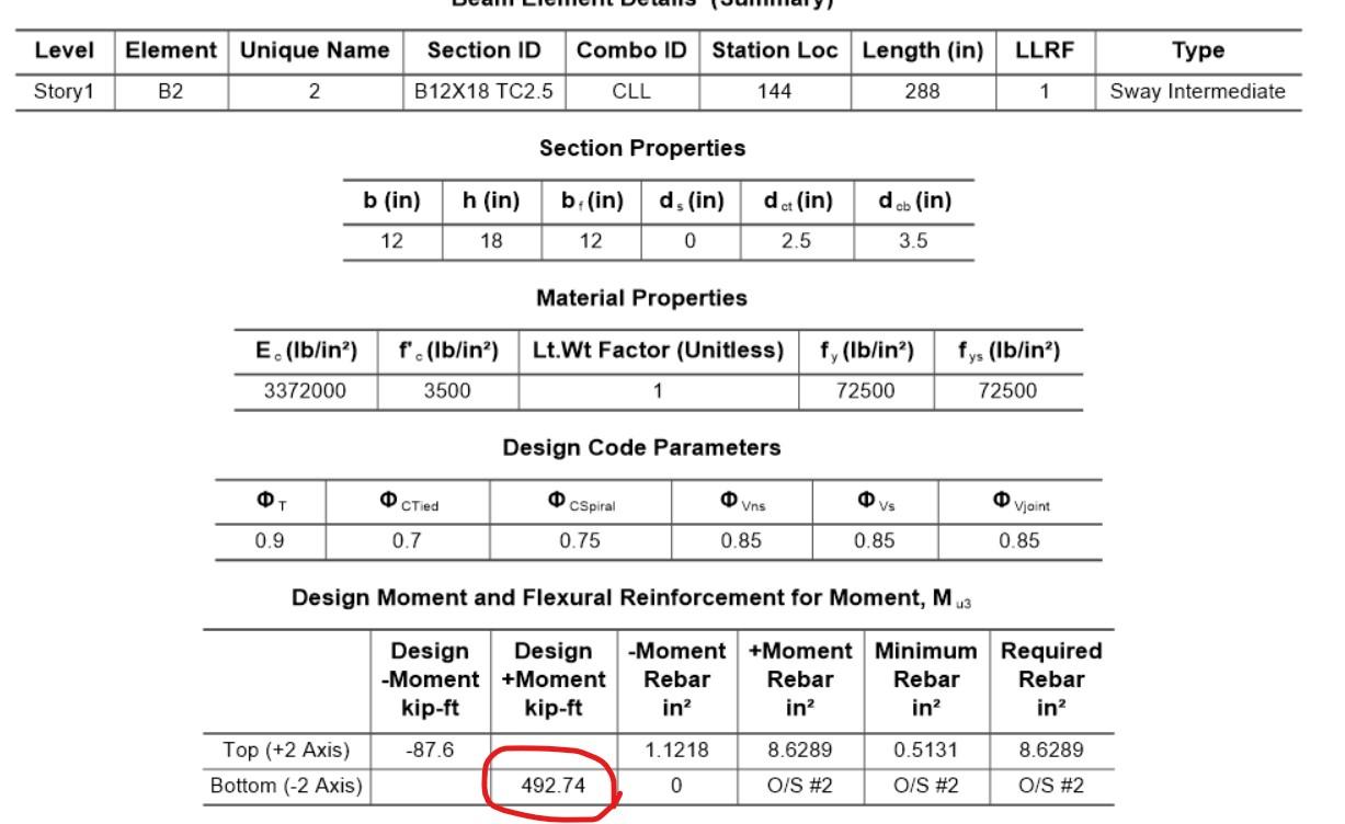
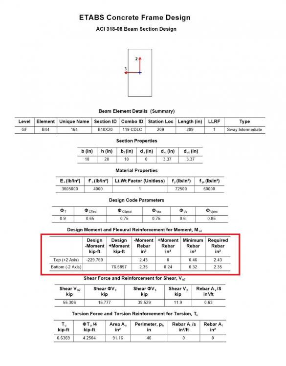
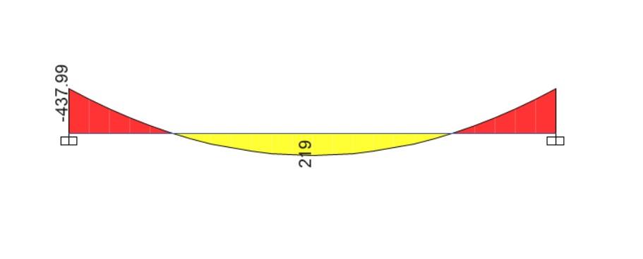
I am trying to understand doubly beam design procedure and failure criteria in etabs A 24 ft long, 12"X18" beam fixed at both end subjected to load of 9.125 kip/ft, yield maximum positive moment 219 kip-ft at mid span and maximum negative moment 438 kip-ft at support. But while designing at mid span Etabs is designing for 492.74 kip-ft instead of 219 kip-ft (Image b). Can anyone tell me why?

-
Beam deflection in Etabs
Saiful Islam Zaber replied to Saiful Islam Zaber's topic in Software Issues
Yes . I am clear . -
Simply Supported Beam Model As Shell Element
Saiful Islam Zaber replied to Saiful Islam Zaber's topic in Concrete Design
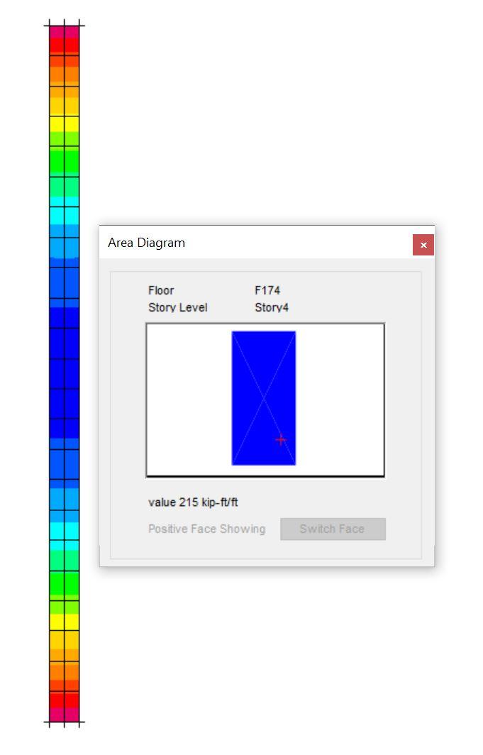
@UmarMakhzumi Thanks a lot. As there are two type of shell in Etabs - horizontal and Vertical ( Slab and Wall ) , Modelling the simply supported Beam by Slab Shell shows 216 kip-ft moment which is correct but Wall type shows 138 kip-ft which is not expected. That brings the question " How should I model link beam between Shear wall or How should I model Deep Beam or swimming pool hanging from a large depth beam (but not Deep beam) bottom, as Slab or Wall?"

-
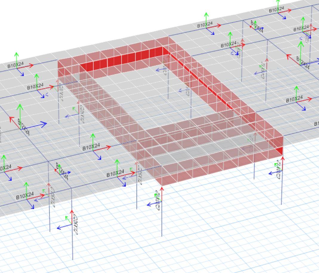
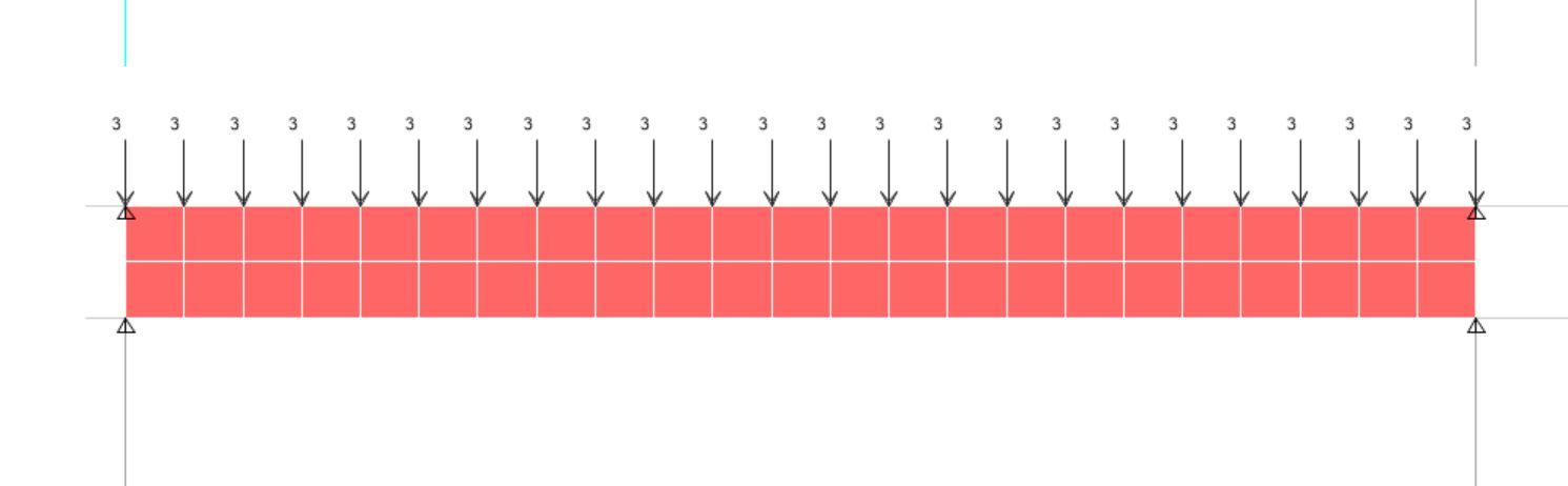
I am trying to understand Shell element behavior . I have modeled a simply supported beam of 24 ft with 1ft thick shell element (Depth 2ft). Meshed Along length 24 and 2 along depth. Applied 3 kip point load at Node along top surface to create a 3 kip/ft loaded simply supported beam of 1 ft Width X 2 ft Depth. Assigned the beam as spnadrel. In my opinion Moment wrt to major axis should be = 3*24^2/8 = 216 kip-ft/ft But according to etabs moment is 138 kip-ft moreover the diagram is rectangular . Can anyone explain please??


-
How to model mat on pile cap on SAFE ? Does anyone have similar experience ?
-
Saiful Islam Zaber reacted to a post in a topic:
Connecting Building With Bridge
-
Saiful Islam Zaber reacted to a post in a topic:
Connecting Building With Bridge
-
Connecting Building With Bridge
Saiful Islam Zaber replied to Saiful Islam Zaber's topic in General Discussion
Floor level of building & Floor level of Bridge is same .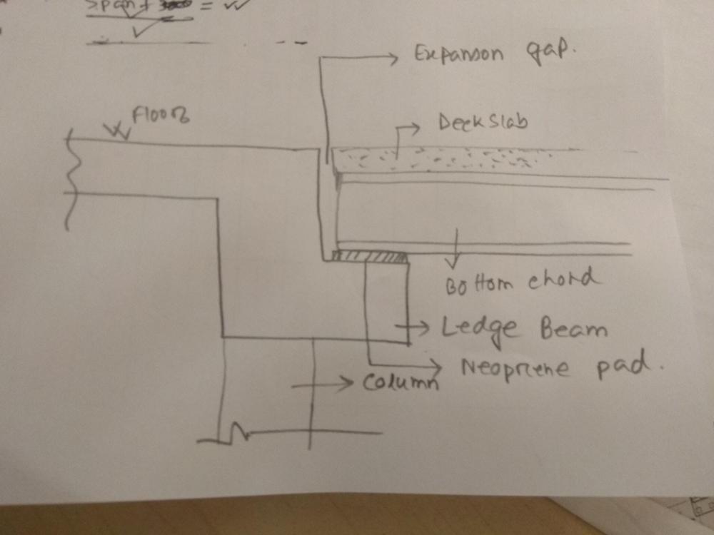
-
Saiful Islam Zaber reacted to a post in a topic:
Column Design In Etabs
-
Connecting Building With Bridge
Saiful Islam Zaber replied to Saiful Islam Zaber's topic in General Discussion
Roller End of the bridge Will be on neoprene Pad on column capital and hinge end of the truss will be on column capital attached with anchor bolts. Actually there are three bridges , One of them will rest on beam , the Support reaction is about 35 ton . We have decide to make ledge Beam to support bridge. But the problem is beam depth is also limited to 24 in by architect. -
Saiful Islam Zaber reacted to a post in a topic:
Pile Design
-
UmarMakhzumi reacted to a post in a topic:
Reference Point in ETABS
-
Saiful Islam Zaber reacted to a post in a topic:
From Palestine with love <3
-
I am designing a skybridge connecting two buildings at 20m above ground. Bridge length is 22m. The Bridge is double storied. One Supporting end will be hinge support and another roller ( as there will be expansion gap). Does anyone have similar type of experience.. ??
-
while all the beam are connected concentrically to column how can there be such large minimum moment ?? See the Column in grid E4 8.bmp
-
Reference Point in ETABS
Saiful Islam Zaber replied to Saiful Islam Zaber's topic in Software Issues
1) Go to Modify/Show grid >>On Top Right Corner go to reference Points >> Select then Delete . 2) First method shown in this PDF is available in Etabs, Both metgos are available in SAP 2000 Non Uniform Load.pdf -
After Releasing moment M22, M33 on both end, why Etabs is still designing for M22. Combination = 1.4DL+1.7LL ?? What is Minimum M22 & M33 Col.pdf