.png.1a89478215d8f40d1a47f71924da88bb.png)

Sami Ullah Khan Bangash
-
Posts
19 -
Joined
-
Last visited
-
Days Won
4
Recent Profile Visitors
2573 profile views


Sami Ullah Khan Bangash's Achievements
")
Newbie (1/14)
7
Reputation
-
 Sami Ullah Khan Bangash changed their profile photo
 -
 Sami Ullah Khan Bangash reacted to a post in a topic:
Beam/column Capacity
Sami Ullah Khan Bangash reacted to a post in a topic:
Beam/column Capacity
-
Sami Ullah Khan Bangash reacted to a post in a topic:
Torsion: Reinforced Concrete Members
-
Sami Ullah Khan Bangash reacted to a post in a topic:
Overlapping volumes at slab beam junction
-
Fatima Khalid reacted to a post in a topic:
CUREE literature on seismic research
-
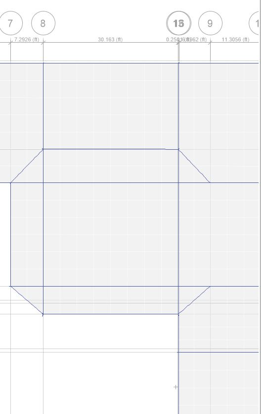
AOA everyone, Apart from assigning the usual stiffness modifiers of 0.35 for beam, 0.25 for slabs etc , should we assign mass and weight modifiers to beams? Or does ETABS automatically account for overlapping volumes of slab at beam center line? Also should I be taking torsion modifier for ALL the beams as 0.1? and for complex frame structures where there are irregular or non-orthogonal beams, should I take torsion stiffness as 0.1 at all? I mean how do I know if its a case of compatibility torsion or equilibrium torsion. I am attaching a snapshot of the frame. See the chamfer edge at grid 8. Thanks

-
Sami Ullah Khan Bangash reacted to a post in a topic:
Raft Modifier
-
EngrUzair reacted to a post in a topic:
CUREE literature on seismic research
-
Sami Ullah Khan Bangash reacted to a post in a topic:
Dynamic Analysis
-
UmarMakhzumi reacted to a post in a topic:
CUREE literature on seismic research
-
http://www.curee.org/ Go to this website to access tons of free research material on seismic research. Unfortunately, CUREE will pack up soon at the end of this year so benefit from their decade's worth of experience. and also teach me a thing or two at the end lol. JazakAllah Khair. Regards
-
Sami Ullah Khan Bangash reacted to a post in a topic:
The Most Common Errors In Seismic Design & Their Avoidance
-
Sami Ullah Khan Bangash reacted to a post in a topic:
Aci 21.1.1 Energy Dissipation Confusion
-
Strip moments in Safe
Sami Ullah Khan Bangash replied to Sami Ullah Khan Bangash's topic in Software Issues
AOA @Rana Waseem. Thanks for your reply. Well, the strip width in safe was the same as in ACI i.e 1/4th the span on both left and right of column centre line. This was program default but I confirmed the 1/4th rule by checking up strip geometry menu. I am guessing the issue is because SAFE is probably only displaying the slab moment minus the beam moment for column strip. Is this true? Regards -
Sami Ullah Khan Bangash reacted to a post in a topic:
Strip moments in Safe
-
UmarMakhzumi reacted to a post in a topic:
Strip moments in Safe
-
Sami Ullah Khan Bangash reacted to a post in a topic:
Limitations of casting reinforced concrete slab
-
Sami Ullah Khan Bangash reacted to a post in a topic:
Limitations of casting reinforced concrete slab
-
Strip moments in Safe
Sami Ullah Khan Bangash replied to Sami Ullah Khan Bangash's topic in Software Issues
Well thanks anyway. I can work with this much information so far. IA Regards, -
Strip moments in Safe
Sami Ullah Khan Bangash replied to Sami Ullah Khan Bangash's topic in Software Issues
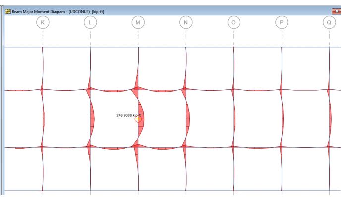
@UmarMakhzumi Well cant say for sure whats happening here. But middle strip moments match with the manual results. For column strip, the software mid beam moments are still higher than manual. manual gives 151kft and the software value is 248kft. However, when I apply stiffness modifiers to beams and columns (0.35 and 0.7) respectively, the beam moment drops to around 209kft but still appreciably greater than manual. @Rana Waseem what do you think is the issue here? @UmarMakhzumi umar bhai how do you evaluate slab and beam moments for two way slabs? like what is your take on this? Regards, -
UmarMakhzumi reacted to a post in a topic:
Strip moments in Safe
-
Strip moments in Safe
Sami Ullah Khan Bangash replied to Sami Ullah Khan Bangash's topic in Software Issues
After hours of miserable pondering I came up with this lol. Correct me if I am wrong. The strip moments are shown only for the slab portion of the slab minus the beam moments. Summing up the beam and strip moments will give us the equivalent of column strip moments that we obtain through typical manual equivalent frame analysis. For middle strip, the moments are obviously for the slab only since no beam is present. Thanks. -
Strip moments in Safe
Sami Ullah Khan Bangash replied to Sami Ullah Khan Bangash's topic in Software Issues
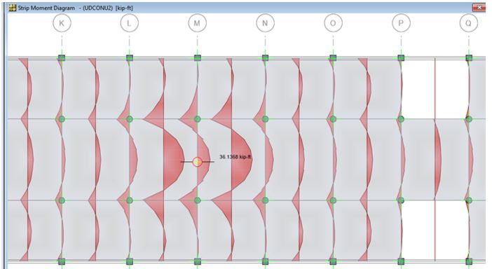
I am talking about the span in Grid M. only the interior spans LM and MN were loaded with live load while dead load was uniform on all spans. I did this to obtain maximum positive moment on interior column strip at grid M. However, the strip moments being displayed are too low to make sense. -
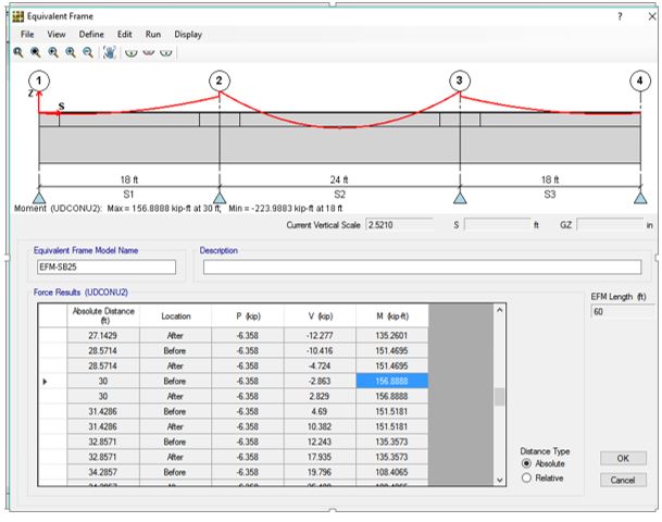
AOA, I have been trying to figure out why strip moments (last figure) are so low compared to either beam moments or the equivalent frame method moments (2nd figure). I also checked the strip moments manually using equivalent frame method technique but the moments were way higher than the 36 Kft shown in strip moment diagram. Am i modelling the design strips wrong here?? Appreciate the help. Regards.
-
UmarMakhzumi reacted to a post in a topic:
beam moment M3 (maximum and minimum)
-
beam moment M3 (maximum and minimum)
Sami Ullah Khan Bangash replied to Sami Ullah Khan Bangash's topic in Software Issues
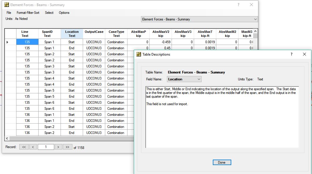
Bulls EYE!! Umar bhai your line of reasoning was right on. lol. I tried to find stuff in safe analysis reference manual but no luck. but then found this( attached in the photo below). Turns out the max and min are just end moments for each of the start, middle and end regions. I also confirmed this by moving the cursor over the bmd in those regions and comparing the values being displayed. They matched. What a relief.!! Thanks a tonne. (Y)
-
beam moment M3 (maximum and minimum)
Sami Ullah Khan Bangash replied to Sami Ullah Khan Bangash's topic in Software Issues
AOA Umar Bhai, Start , middle and end just like in the table. although in graphical view, it can show the full BMD and if i move the cursor across the beam, it can display value of moment/ shear at almost any location. -
AOA, I have attached the beam moment and shear envelop summary for a concrete frame structure modelled on safe. Only a single load combination was defined for dead and live load cases: 1.2D+1.6L. However, the table shows two moments: max and min M3. (but only one value for shear and torsion?) How were these two values calculated? Shouldnt there be a single unique moment and shear configuration for a single load combination? thanks

-
Uzair bhai can you please mention company name, contact no, name of senior engineer etc? Regards, Sami Ullah Khan Bangash
-
Ostruc.com seems down?? Any issues with that
-
Ayesha reacted to a post in a topic:
moment of inertia at slab-beam-column connection
-
AOA, According to ACI 318-11 R8.7.1 stiffness to be used for braced frames should be EI/2 for beam members and full EI for column members. Also the code mentions the stiffness increment factor of 1/( 1- c2/l2)^2 for beams for the segment starting from column center line to face of column. In equivalent frame method of 2 way slab design, it also mentions that moment of inertia of column from mid of slab to bottom face of adjoining beam be taken as infinite. Now based on above provisions, should I typically model the joint as rigid uptil beam and column offsets? Another option i was thinking was to model the joint in separate segment and assign stiffness factor to that segment only. But it seems a pretty cumbersome process. Should I be modelling both the rigid joint connections as well as assigning reduced moment of inertia factors to the rest of the member regions? thanks for the support
-
^ thanks brother.