

Saad Pervez
-
Posts
39 -
Joined
-
Last visited
-
Days Won
8
Recent Profile Visitors
2082 profile views


Saad Pervez's Achievements
")
Newbie (1/14)
23
Reputation
-
 Saad Pervez reacted to a post in a topic:
Parking Roof Collapse
Saad Pervez reacted to a post in a topic:
Parking Roof Collapse
-
Can you share your model? because I have never seen this warning before.
-
UmarMakhzumi reacted to a post in a topic:
Steps in slab
-

etabs disconnect joint connectivity in Etabs
Saad Pervez replied to Mirza Adeel's topic in Students Zone
Then don't connect them? Stop your wall before this joint? -
If you can design this slab with a 7" thickness, there is no need to provide a beam in the step region, because again a 14" depth won't be sufficient for a 30' span. And your beams would be projecting out on top of the wall, which is not very good from an aesthetic point of view. Drop below the slab can also obstruct MEP services. This is a personal point of view by the way, technically you can provide beams in the steps region.
-
1) Its behaviour would be one way or two way? Depends on your design but 6" slab over a 20'x30' span is not fulfilling ACI's minimum depth requirements. 2) Is there any special detailing required in steps region? yes 4) The left side beam is rectangular-beam and right side beam is T-beam? left side is an inverted beam
-
Vamshi reacted to a post in a topic:
FEM- internal meshing
-
UmarMakhzumi reacted to a post in a topic:
FEM- internal meshing
-
Saad Pervez reacted to a post in a topic:
FEM- internal meshing
-
No specific information is available on this topic. However, judging by CSI's answer to this question: https://wiki.csiamerica.com/display/kb/Subdivide+frame+objects each frame is treated as a discrete element, and by default, auto meshing is done at internal points and/or intersecting frames which can also be turned off.
- 3 replies
-
- 2
-
-
- fea
- internal mesh
- (and 2 more)
-
Difference between Etabs 9.6 vs Etabs2015
Saad Pervez replied to Alhamdu Abdella's topic in Concrete Design
First, be sure of the units. Second, there is no difference between two. ETABS 13 and onwards, they increased the non linear capabilities so it 'wont effect most of the users' as they say in their manuals. You can refer to release notes to find the new enhancements/changes. Also make sure, the design code, reduction factors and load combinations you are using in newer version are right. -
Saad Pervez reacted to a post in a topic:
9th International Civil Engineering Conference (ICEC 2017), December 22-23, 2017, Karachi, Pakistan
-
Response spectrum analysis is a linear-dynamic statistical method of analysis. Use the flow chart below to determine if you need to do dynamic analysis for your structure or not.

-
Saad Pervez reacted to a post in a topic:
ETABS 9.7.4 Runtime Error Message
-
UmarMakhzumi reacted to a post in a topic:
ETABS 9.7.4 Runtime Error Message
-
Slab element number during analysis and slab area labels are different. Slab number during analysis is the position of that element in the database, slab area labels have the notation F### and usually indicate when this particular element was drawn, slab area labels can also be repeated in different stories, slab element number is unique. Exporting to EXCEL will also not help because EXCEL will slab area labels, not slab element number. Exporting the model to .e2k and the importing it back might help, OR you can do a manual check of all your model by studying the mesh. In my experience, this error is caused by a shell element with 2 nodes only, which happens when you move one set of points to already existing points by move command, this will merge the points but the element defined between them stays in the database. Hope this helps.
-
Section 14.3.2 and the minimum limit of 0.0015 applies to walls that are not resisting shear. If the wall is resisting horizontal shear forces in the plane of the wall, section 11.9.9.4 applies, and vertical reinforcement should be minimum 0.0025 times the gross concrete area.
-
UmarMakhzumi reacted to a post in a topic:
Updates to Member Roles
-
Waqar Saleem reacted to a post in a topic:
Updates to Member Roles
-
Glad to be on board
-
Kainaat reacted to a post in a topic:
Centre to Centre Modeling
-
WR1 reacted to a post in a topic:
Centre to Centre Modeling
-
UmarMakhzumi reacted to a post in a topic:
Centre to Centre Modeling
-
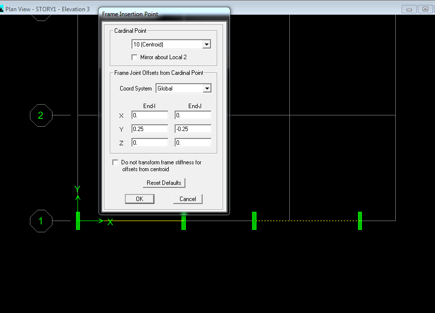
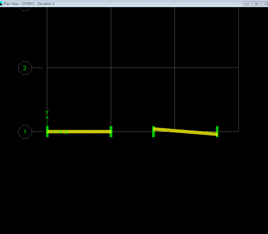
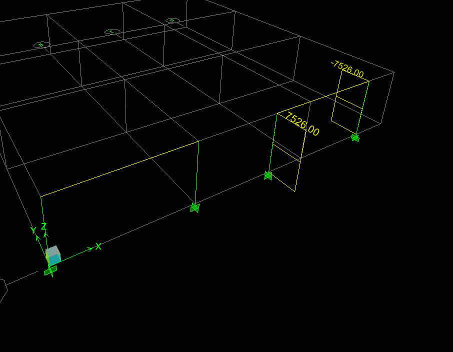
You should do center to center modelling for this structure and to capture the eccentricity, you can either model the column as shell element like Sir Rana said or you can use insertion points for beams, always look at the extruded view to know the actual arrangement of the elements you're modelling. I'll illustrate the use of insertion points, you can use the approach you find suitable. Insertion points will capture real world behavior by keeping your Finite Element model closer to reality. Consider the 2 beams below, the are exactly the same, they look exactly the same. We'll select the beam on the right hand side and go to assign>frame>insertion points. And "insert" the beam with eccentricity of 250 mm at both ends. End-I with a positive eccentricity and End-J with a negative eccentricity, (don't forget to uncheck the box!) Then we look at the extruded shape again, we notice that the beam is inclined now (which matches your case). If we look at the "unextruded" view, both beams will look the same. We run the model, we can see that the values for shear force are different because ETABS is calculating forces based on inclined length. If eccentricity is captured, there should be a moment in 2-2 direction. Which we can see is there and is numerically equal to P*e = 30103.99*0.25 = 7526 kN-m Hope this helps.


-
Saad Pervez reacted to a post in a topic:
Difference between tension controlled and under-reinforced sections
-
Sag rods will restrain translation, you can draw points where sag rods are connected, divide the frames at those points and apply vertical translation point restraint only.
-
Thickness of Base Slab - Retaining Wall
Saad Pervez replied to Hira Malik's topic in Concrete Design
According to ACI 318-08 Cl 10.5.3, you can ignore the minimum reinforcement requirement if As(provided)>1.33 As(required). You can use this provision in your favor if you want. -
Thickness of Base Slab - Retaining Wall
Saad Pervez replied to Hira Malik's topic in Concrete Design
thickness of base slab itself, isn't 6 ft the height of your retaining wall? -
WR1 reacted to a post in a topic:
Quantity Takeoff software
-
You can take off quantities from etabs as well, I have worked on BlueBeam Revu, quantity take off is severely limited, you still have to draw and mark everything on plan, it is not automatic.
