spatio99
-
Posts
7 -
Joined
-
Last visited
-
Days Won
1
Recent Profile Visitors
882 profile views


spatio99's Achievements
")
Newbie (1/14)
3
Reputation
-

Unable to apply line loads on concrete slabs in ETABS and SAFE
spatio99 replied to spatio99's topic in Software Issues
Thanks Engr. Uzair. I'll try that approach. -
 spatio99 reacted to a post in a topic:
Unable to apply line loads on concrete slabs in ETABS and SAFE
spatio99 reacted to a post in a topic:
Unable to apply line loads on concrete slabs in ETABS and SAFE
-
spatio99 reacted to a post in a topic:
CSI SAFE FINITE ELEMENT DESIGN INTERPRETATION
-
I'm designing a flat slab structure with perimeter cladding that is to be anchored to the edges of the slab. The external cladding has a total weight per meter run of 5 KN/m. How can I apply this load to the slab edges so as to model the true behavior of the slab under loading in order to get accurate results from the analysis?
-
WR1 reacted to a post in a topic:
CSI SAFE FINITE ELEMENT DESIGN INTERPRETATION
-
WR1 reacted to a post in a topic:
CSI SAFE FINITE ELEMENT DESIGN INTERPRETATION
-
CSI SAFE FINITE ELEMENT DESIGN INTERPRETATION
spatio99 replied to spatio99's topic in Software Issues
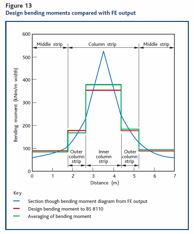
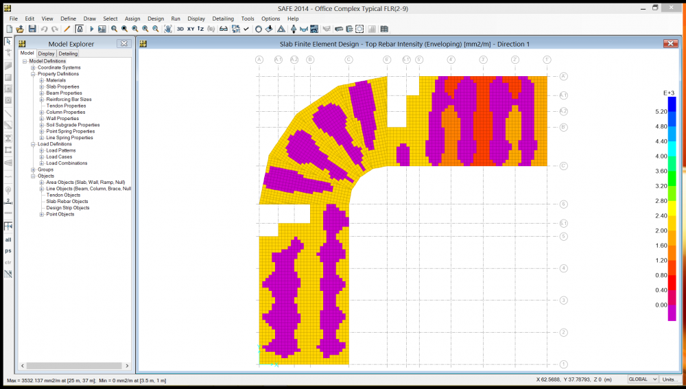
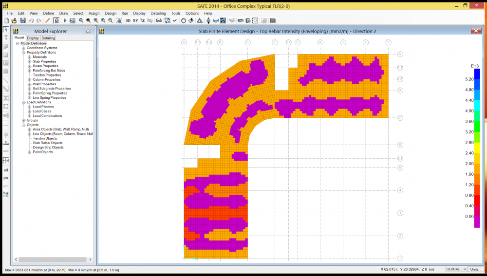
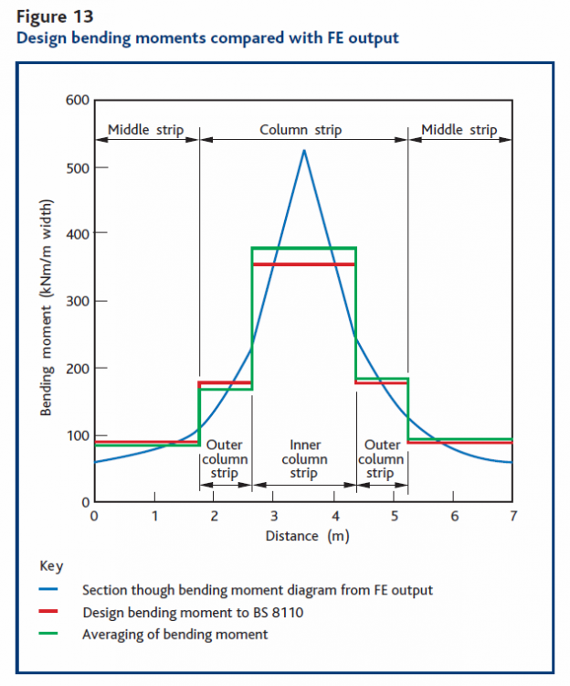
I tried something else, From The Concrete Centre publication "HOW TO DESIGN REINFORCED CONCRETE FLAT SLABS USING FINITE ELEMENT ANALYSIS by O Brooker" in pg.13 "An alternative method is to simply average the bending moment over a width of slab. However, if designing to Eurocode 2 the requirements of Cl.9.4.1(2) should be adopted. The widths of these strips can be determined by the designer; an example is shown by the green line in Figure 13. Here the same strip widths as the BS 8110 method have been adopted to show how the results compare. This method has the advantage that it can be used for a slab with irregular geometry, because a fixed bay width is not required. It can also be used with area of steel results, removing the need to calculate the reinforcement areas by hand. It will be seen that both methods give a similar distribution of reinforcement when applied to the same strip widths." I used a Max. Average width of 1m and got the following results.....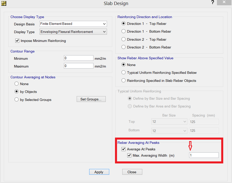


-
spatio99 changed their profile photo
-
CSI SAFE FINITE ELEMENT DESIGN INTERPRETATION
spatio99 replied to spatio99's topic in Software Issues
Thanks Rana Waseem, that is a brilliant response. I'll remodel the strips with respect to the local axes I assigned to the slab panels to get proper mesh transitioning and re run the analysis, design and detailing. I'll share the results when I'm done. The only problem with the strips is that there is no flexibility in modelling the exact width needed as the start and end points only have (x inputs) would have been better if there was an option for (x,y inputs). More so the Auto Widen Strip function does not help much with strips at angles other than 0 or 90 degrees. I'll try out some configurations and post the results. Back to the Finite Element Analysis Solution. In this day and age I seriously doubt the possibility of a Structural Engineer not coming across complex floor systems. Architects and Engineers alike can be very imaginative (we can't hide from it ). From The Concrete Centre publication "HOW TO DESIGN REINFORCED CONCRETE FLAT SLABS USING FINITE ELEMENT ANALYSIS by O Brooker" in pg.12 "Interpreting results: The results from an FE analysis will generally be in the form of contour plots of stresses and forces, although a ‘section’ through the contour plots (either bending moment or areas of steel) can usually be obtained. These will show very large peaks in bending moment at the supports. The temptation to provide reinforcement to resist this peak moment should be avoided. This potential error stems from a lack of understanding of the assumptions made in the modelling. The reinforcement in the concrete will yield at the support position and the moment will be distributed across a larger area; it is not therefore necessary to design to resist this peak moment. However, a method is required for distributing this peak moment across a larger area." I would like to share the PDF with you but I'm not sure about the forum rules concerning that. From the above statement, the large intensities I'm getting at the Beam/Column supports (joints) are to be expected but then it still takes me back to my initial question, "How do I use the plot to provide reinforcement for the slab?" More so, the concept of "AVERAGING" keeps popping with FEA Solutions. Let's say for instance we don't have the luxury of adding strips and the only option is to use FEA to design the slab, how would you do it ? If there is an approach on how to get this done it would be greatly appreciated. Thanks for your anticipated response. -
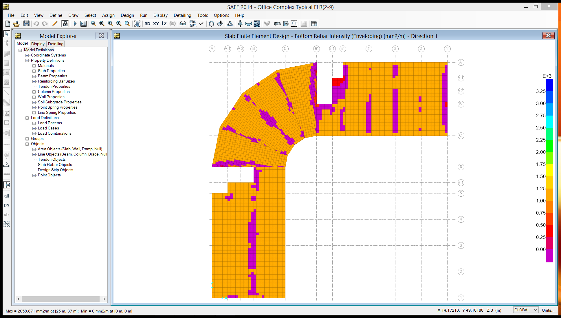
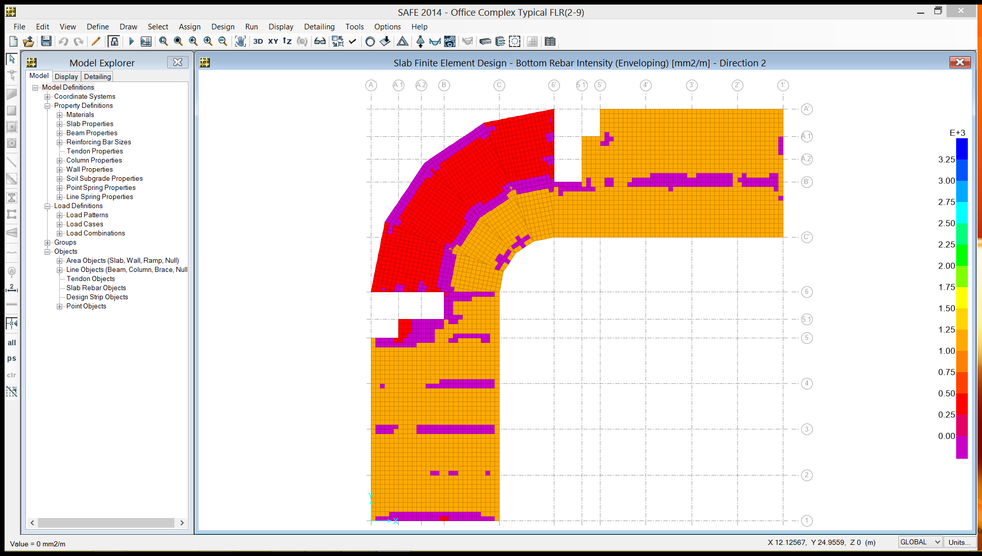
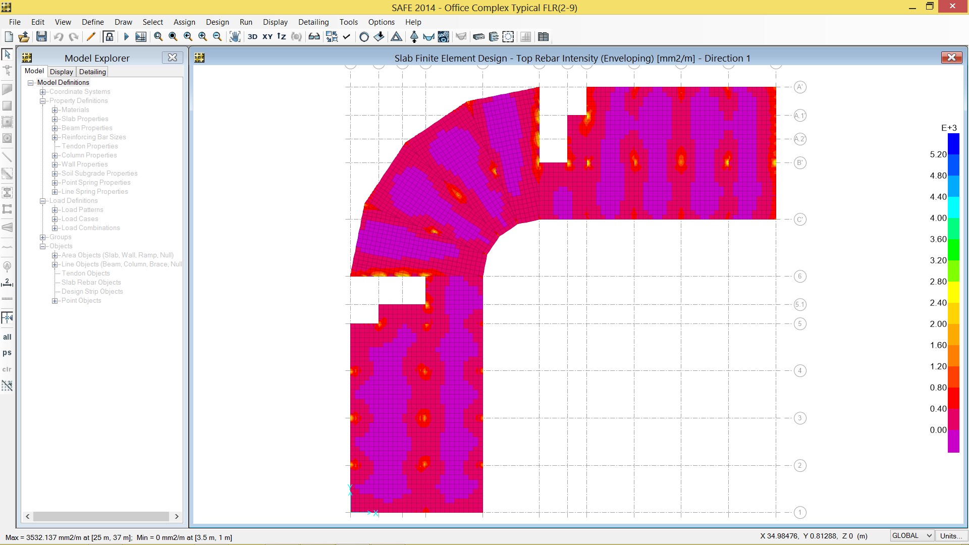
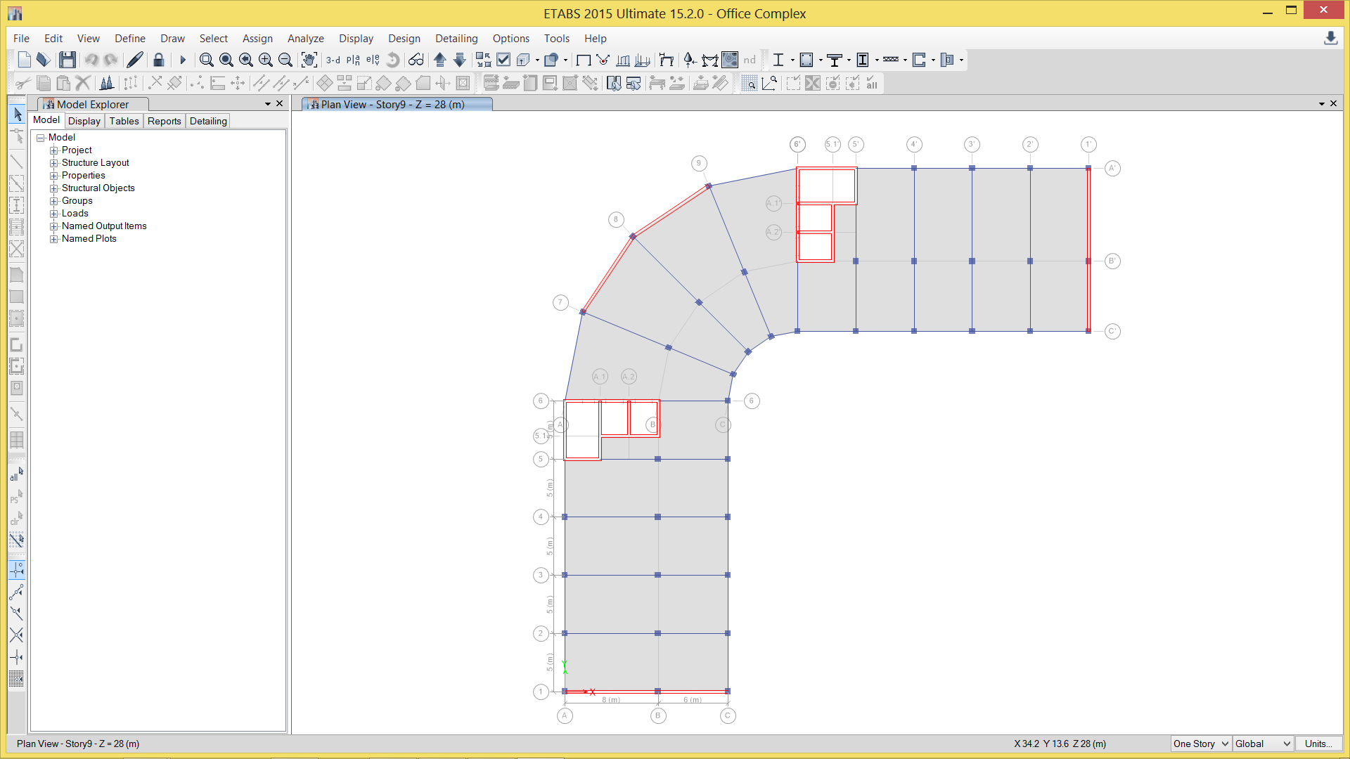
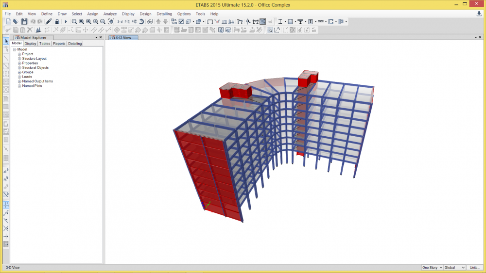
Hello Guys, I'm finding it difficult interpreting the rebar intensity contour plots (direction 1 and 2) generated by CSI SAFE after finite element design of a slab. I'm getting intensities as high as 3500 mm2 per m at column joints. How does one provide reinforcement for a slab using the contour plots. I've attached some screenshots of the model for viewing(can provide more if needed). I designed the structure to BS8110. Any materials (PDFs, Videos, Links, Examples...) to help me understand the concept especially how to provide reinforcements from the contour plots would be greatly appreciated. I've already tried adding strips but the details generated for the slabs in the radial part of the structure is not concise. My plan is to get the reinforcement from the Finite Element Design and detail the slab with Tekla Structures because of the ease of modelling reinforcements in virtually any angle. Thanks for your anticipated responses.


-
EngrUzair reacted to a post in a topic:
Steel Connection Design
-
Engr. Uzair, thank you very much the links you provided were very helpful.
-
spatio99 reacted to a post in a topic:
Steel Connection Design
-
Does anyone know a steel connection design software that designs every type of connection to BS 5950 or Eurocode 3 and can interface with SAP 2000 or CSI ETABS