

Alinalysis
-
Posts
22 -
Joined
-
Last visited
Alinalysis's Achievements
")
Newbie (1/14)
2
Reputation
-
 UmarMakhzumi reacted to a post in a topic:
How to solve bending moment probelm ETABS
UmarMakhzumi reacted to a post in a topic:
How to solve bending moment probelm ETABS
-
Omer Ahmed reacted to a post in a topic:
How to solve bending moment probelm ETABS
-
Thanks to all of you I have an idea now how to look at the support condition. Now last question, in the three analysis models 3D, 2D, and continuous beam with pinned supports, if I made a condition for analysis in each model which could give me different design moments, will the design still be economical and safe for each type ? Thank you
-
Alinalysis reacted to a post in a topic:
Connection between elements
-
Alinalysis reacted to a post in a topic:
Connection between elements
-
Alinalysis reacted to a post in a topic:
Pile design
-
Thanks you that cleared some concept for me May I ask another question, Is there any difference in analysis between modeling a building in 3D using any FEM software, and modeling one frame only, or modeling as separate elements (and just considering the analysis for gravity loads) To make it clear, we have three story building, now let's model it using a 3D software. Ok, now if we split the building into frames, we can see beams and columns. Now split the frame into separate elements, Continuous beams with pinned supports only. Is there going to be difference between these three modelings with respect to analysis results which will affect the design results. Thank you
-
Alinalysis reacted to a post in a topic:
Connection between elements
-
Hello I would assume that the column will not allow rotation therefore there will be moment developed
-
Alinalysis reacted to a post in a topic:
Connection between elements
-
I created a simple model to see how does the properties of column would affect on the support conditions. When increasing to size of columns (increases stiffness?) the column will carry more moment. When decreasing the size the carrying moment will decrease, until it gets to zero. So does that mean when increasing the size it will increase the stiffness of the moment and the column will act as fixed support ? And when decreasing the size the column will act as hinge ? (I guess that's why I got that shape for bending moment in the third picture)
-
Alinalysis reacted to a post in a topic:
Connection between elements
-
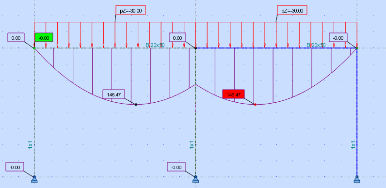
I'm back and I've done the example So I created three cases 1) beam 20X50, columns 30x40 2) same beam size, columns 1x1 and I got results as a simply supported beam , M = 30x5^2/8 = 93.75 3) continuous beam with three columns 1x1 but got a an unexpected result (maybe I'm wrong?)
-
Alinalysis reacted to a post in a topic:
Connection between elements
-
Alinalysis reacted to a post in a topic:
Connection between elements
-
Thanks, will do this and post the results
-
What if I want to design a full building, in structural software by default the connection will be fixed. I found this on steel construction webpage http://www.steelconstruction.info/design#Braced_frames As far as i understood if we provide bracing to a steel structure, then we can consider the beams to be simply supported ? what about concrete structures I am asking these questions because I'm confused, when I want to design a building using software, do I need to change the supports and connection of elements to pinned connection or leave them as default. Thank you
-
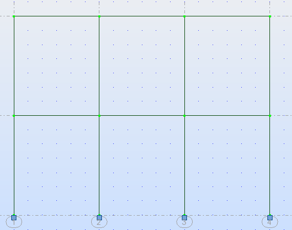
So Let's say we have three storey frame, three beams per storey In my concrete design course, I would take the first floor beams and draw my columns as pin supports like this As you said this is just for simplifying right? So the way that it's being analysed is taking the whole frame and analyzing it, so there will be some moments acting on columns. And does reducing stiffness will reduce the moment transfer ? Thank you

-
Hello What type of connections are there between two structural elements, let's say for example connection between concrete column and beam. In my concrete design course the assumption was that when analyzing a continuous beam the columns would act as pinned support, why we make this assumption ? is it just for making the analysis easier ? What are the other types of connection ? When using analysis software the bending moment value will be different because the columns are not action as pin support, it was said to me that the connection type is semi rigid, so what is semi rigid connection ? and how can i calculate the value of bending moment if the connection is semi rigid. Thank you
-
Hi When assigning the shear wall to act as one wall it gives a moment of 60,000 KNm but when assigning each face of the shear wall (there are 5 faces) the moment will be less than 20,000 KNm for each face which method is correct, assigning it as one member or multiple members
-
Hi I made a calculation for approximate bending moment, I have the load acting on average of let's say 200KN , that will be 200/40 = 5KN/m distributed load and the height of building is ~75m , so M = 5*75*75/2 = 14,000KNm far away from the 60,000~50,000 KNm that I'm getting. I'm confused and don't know why I'm getting this amount of moment My shear wall is 4X6 m in the center of building
-
Thanks my problem is the shear wall didn't reduce the deflection that much so I assume my modeling is wrong. So what i understand is the shear wall should reduce the deflection significantly, that means the deflection of 13mm after adding shear wall is making sense
-
hello all few questions about wind load and shear wall: - does it make sense the wind load leads to deformation o 260 mm for 20 storey 40X20 building ? effective speed ~ 52 m/s, basic speed 24 m/s - when I added the shear it seems that it reduce the deformation to 240 ~ 230 mm is that true ? what's the point of the shear wall if it cannot reduce the lateral deformation ? - the bending moment on shear wall reaches up to 50,000 KNm which leads to the failure of the shear wall, it that amount of moment OK ? I created a model in etabs so maybe I done something wrong so I asked an expert help who modified my model and the deformation reduced to ~ 13 mm and moment to ~ 17,000 KNm [this makes sense to be but I just want to make sure]. so which result is making sense?
-
How to solve bending moment probelm ETABS
Alinalysis replied to Alinalysis's topic in Software Issues
Thank you I asked my professor and I will consider the torsion as the program will calculate the required reinforcement -
How to solve bending moment probelm ETABS
Alinalysis replied to Alinalysis's topic in Software Issues
Hi Omar thank you for yours post I solved the problem by modifying the torsion factor as well as removing the stairs and ramps from model (Any way we will do it manually) your link will be helpful I don't know whether I should design the beam for torsion or not, I had two courses in concrete design but never been taught about this topic