Hira Malik
-
Posts
61 -
Joined
-
Last visited
-
Days Won
8
Content Type
Profiles
Forums
Events
Everything posted by Hira Malik
-
Again, I am not asking why to provide this reinforcement, rather what's the criteria of providing these bars. Can please someone help? Which bar, what length, what angle, etc.
-

Underground water tank base slab as a foundation
Hira Malik replied to Fatima Khalid's topic in Foundation Design
Have you tried working it out manually? I too sometimes get over-punching values from SAFE. The punching values you have attached are for what thickness? As I told you before, 18" thickness should suffice in this case. The axial load values are very good and shouldn't require a 30" thickness. Confirming that your ETABS Model is correct. -
Yes, but I need the criteria for providing diagonal reinforcement. I guess it's provided at 45 degree but not sure where that cam from.
-
WHAT IS THE CRITERIA OF PROVIDING DIAGONAL REINFORCEMENT AT THE CORNERS OF A SLAB-WALL JUNCTION?
-
Yes. And each wall will have soil pressure from outside and water pressure from inside.
-
Not sure about this. Both walls will act individually won't they? Yes the inward water and outward soil pressures on each one wall will cancel each other but not completely. Therefore, I am considering the Culvert as empty to maximize the outward soil pressure.
-
Yes its a culvert with long walls and slab on top. And so it cant be designed as a retaining wall. But due to longer length, main reinforcement will be that along the shorter span i.e. height (vertical reinforcement). I was thinking it should be designed using attached formula for for FEM when performing Moment Distribution, and W will be same as we do for triangular load. I was just confused if I need to use the walls coefficient method but I guess that's for walls with 2-way action which isn't the case here.

-
Those are for 2 way slabs types I guess ? My wall is 17m in span and 1.5m in height i.e. one way and main reinforcement will be along height... so it will be simply designed by taking soil lateral loads as (ka*unit weight*height) right?
-
She is already in contact with me :). But unfortunately I had to get involved on another project, leaving the tunnel design as it was. Still I have shared all the stuff I had with her. I was hoping we have a tunnel design expert here in the group. Really needed.
- 8 replies
-
- 1
-

-
- soil-structure
- sap2000
- (and 2 more)
-
I am trying to do the design of culverts (single and multi cell) using moment distribution method. 1. Confused about how to calculate horizontal and vertical moments in the wall. Which one will govern? 2. ACI 350-01 says use minimum shrinkage reinforcement ratio as 0.003. Which seems to result in #4 bars @4"c/c which seems too much. 3. Can anyone give me the link to download ACI 350-06 ? 4. Any excel sheet or document using moment distribution for culvert design will really help.
-
MOVING AND STATIC LOAD CASE IN SAP2000
Hira Malik replied to Hira Malik's topic in General Discussion
Yes that I have already done because I always work through load combinations but to my surprise, when I made such a combination, it didn't appear in the display frame forces dialogue box. Will try again. JazakAllah to both of you -
I am modeling a culvert in SAP2000. I am unable to define a load case in which I can include both static and moving loads together. Is there a way I can run the model and check results for traffic and other static loads together? Or they can only be checked one at a time?
-
How? How can I select all circular members at once and apply variable intensity of any pressure? Such that its max at top and decreases towards the bottom.
-
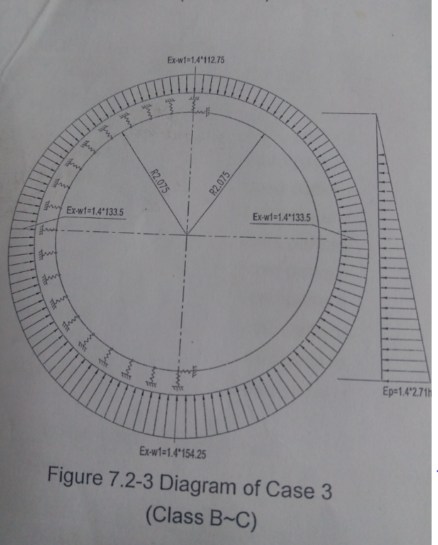
Check the attached model. Rock pressures are as attchaed in previous post. Other loads are as follows: Top and bottom external pressures (kn/m) 2303.5 and 2336.5 Top and bottom internal pressures (kn/m) 863.5 and 896.5 Grout pressure is also attached. No idea why is it only acting at top 120 degrees

-
OK. So is this only for the lateral rock pressure or the other pressures such as internal and external water pressure, and grout pressures be also applied in the 2-2 direction? I will attach the model with the loading details. Kindly check it if you have some time.
-
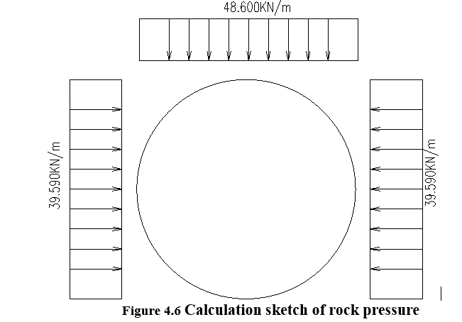
I have attached the screenshot of the loading and how I applied it on SAP. So what I did was simply select the top, left and right frame sections of the tunnel and applied the loading as 39.59 and 48.6 as uniformly distributed load. While applying loads I selected local axis 3. Is it right? Also it confuses me to select the frames for a specific load. Like on how many frame members shall I apply the top loading? And how can I be sure that the members below those will only be used for the lateral loading?

-
Thanx alot for your explained answers. 2. I am designing the tunnel elements as 2D frame sections. So if I apply varying load by selecting one element that will only be for that same element. What I want is that I want to model the whole tunnel as one element somehow, such that when I give value of loading after each distance by selecting all elements, the load is automatically applied as more at bottom and decreases gradually towards the top. I just have 2 values of internal water pressure, 803 at top and 837 at bottom. Want to model them as varying load.
-
SAP2000 is used to model tunnels all the time. How is that the soil or rock forces cant be applied in SAP2000?
-
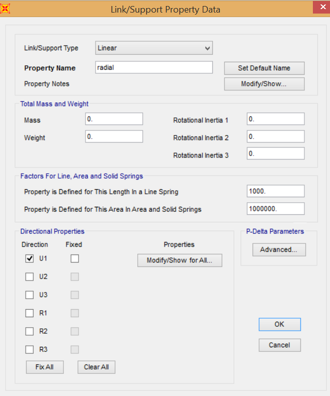
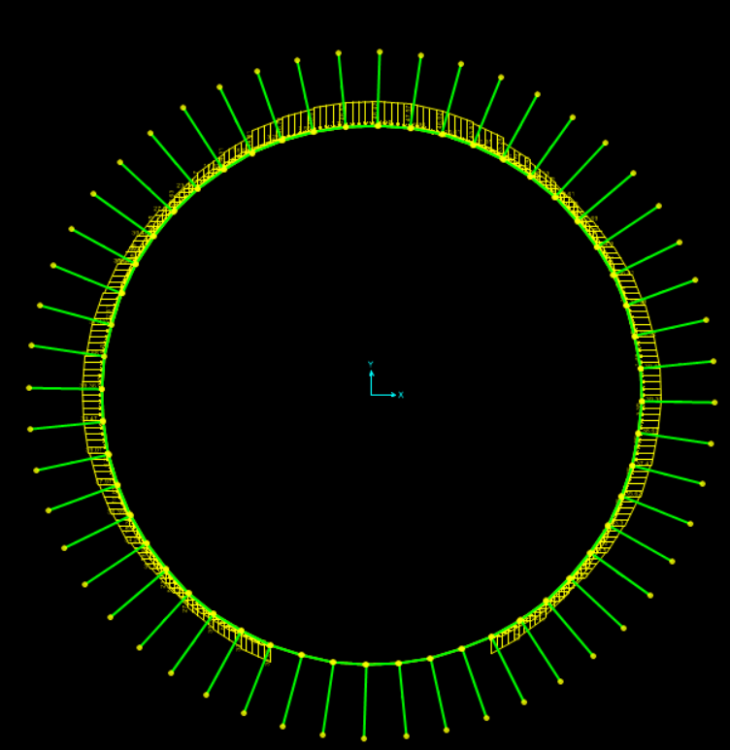
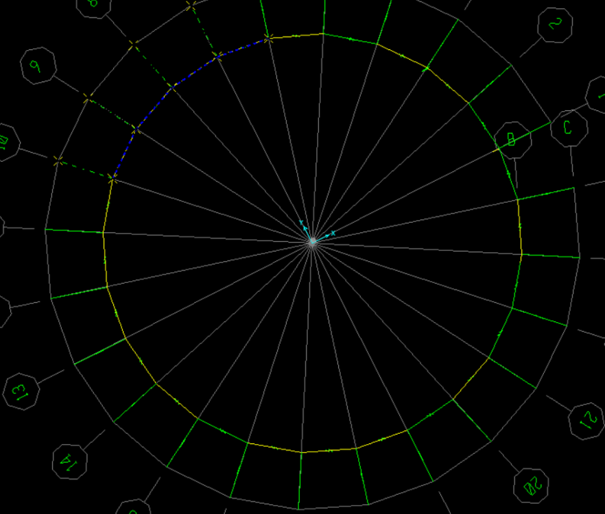
Ohk i got that. Thank you both. Ok i hAve a few more question on the topic, 1. The stiffness is calculated for radial and tangential SPRINGS in the attached pic. That's for circular tunnel. How to calculate stiffness if springs or links are assigned to non-circular sections likes rafts or mat foundations? Whats the formula for STIFFNESS? 2. I have attached another pic of loading. How can I apply varying load on a structure like this? Like load is more at bottom and less at top. To do this, all the members must act as one circle but when i try to join lines, nothing happens. 3. There is also horizontal rock load, and again i have no idea how to apply it on a circular section.


-
Kindly share any material on how to design a tunnel on sap2000. Attached is a pic of a model i found somewhere. this person has braced the tunnel by using "link supports" which I have no idea about since i have ever used them. Whats the purpose of these supports? Its properties have terms like coupled or uncoupled stiffness. and factors for line area and solid springs etc. That image is attached too and the values this person has entered are 1000 and 1000000. Its going above my head. Please guide about this and also how to calculate stiffness and when to define stiffness for a member?

-
wow thats great. thanx a ton !!!
-
I AM TIRED OF SEARCHING WEB FOR TUNNEL DESIGN MATERIAL. GOT ONE EXCEL SHEET WITH SHORT CALCULATION AND NO IDEA HOW THEY DID IT. PLEASE REFER ME TO ANY TUNNEL DESIGN SOFTWARE OR MANUAL EXAMPLES SO THAT I MAY BE ABLE TO UNDERSTAND TUNNEL DESIGN IN DEPTH.
-
Experienced Structure Engineer needed in Lahore with minimum 5 years experience. Our main requirements are for the design of tunnels, prestress bridges, steel structures and power houses. Have you ever designed these or are confident you can do all these structures on your own? Salary will be based on your experience. No extra benefits/allowances will be provided, so its better to apply only if you live in Lahore. Engineers with all these capabilities send your CV at hira.malk@mmpkistan.com
- 1 reply
-
- 3
-
-
job opportunity available at MM Pakistan Lahore office. kindly send your CV and salary requirements at hira.malik@mmpakistan.com
-
I have a 100m by 2m slab resting on a river bed and is uniformly distributed. I want to know: 1. How to calculate the moment as its resting on a bed? 2. Do we need to be provide any reinforcement or such slab can be unreinforced? 3. What is the minimim reinforcement for such slab and where to place it? On top, bottom or middle third as stated in many reference books.