groszni awesome
-
Posts
45 -
Joined
-
Last visited
-
Days Won
3
Content Type
Profiles
Forums
Events
Everything posted by groszni awesome
-
Hello there, Does anybody know how to model honey comb beam in staadpro? Or do i just model them as prismatic section with its section properties follows the HCB? Regards, Groszni
-
Been searching for a while found nothing. I changed the system to common rafter with alot of addition weight. But im still curious with this system just incase ill meet it up in the future.
-
Hello there SEpakistan, Im designing a long span structure for roof, this just an alternative instead of using PEB. The span of structure is 53m and its monosloped. I know in this case gravity loads will govern. DL = 30 kg/m2 and live loads 58 kg/m2. I tried to model this structure in staad pro with lattice girder with bottom and top chord using T section, and vertical and diagonal with double angles. Because the top and bottom chord will be continous when jointed with vertical and diagonal member, so i just add the truss spec to the diagonal and vertical member as a truss. When i run the analysis, the top chord and bottom chord behave just like a beam on the outer fiber. near the support the top chord got tension forces and bottom chord got compression forces, and on the mid of span the top chords is in compression and the bottom chord is in tension, i modeled this a rigid to column. My question is how do i apropriate design this lattice girder? Did i do it wrong? I need some explanation on how this kind of system works. Thank you. Regards
-
Maybe cuz its a requirement for the detailing purpose based on the code. What code did u use to design the beam?
-
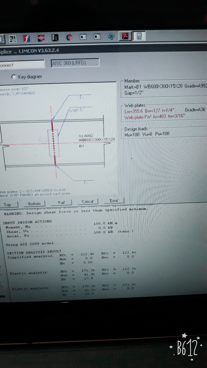
Hello there SE Pakistan, Im designing welded moment splice connection using Bentley LIMCON, and i found these kind of SECTION RESULT ANALYSIS on the report, There are this simplified analysis, elastic analysis and plastic analysis. I just wanna know how do you calculate required load in elastic analysis and plastic analysis??? Cuz i figured it out how to calculate it with simplified method, to find the nft(flange tension) using Mu/(d-tf) + 1/2Pu and nfc(flange compress) using Mu/(d-tf) - 1/2Pu, because on the other result (elastic and plastic method) they gave me significant different result.
-
Web sidesway buckling and web compression buckling
groszni awesome replied to groszni awesome's topic in Steel Design
thank you uzair really helpful -
Classification of beam based on height and spans
groszni awesome replied to groszni awesome's topic in Concrete Design
found this on ACI 318, so whenever the h of beam is <1/4L means that its an ordinary beam right? -
Hello Sepakistan, i wanted to know the Classification of beam based on height and spans, for example when the h and L ratio is large they called this deep beam and so on. Sorry for such a question. Thank you, Regards, Groszni S
-
Assalamualaikum, Im designing a connection beam to column and in AISC 360 sec J10 there are some parameteres we got to check on the column, such as web sidesway buckling and web compression buckling. Ive been searching anywhere in the internet but didnt find any failure illustration of these parameters. Could some of you please draw the failure illustration of sidesway buckling and web compression buckling? Thank you.
-
BEAM COLUMN CONNECTION LIMIT STATES
groszni awesome replied to groszni awesome's topic in Steel Design
no its not an end plate connection i guess, the beams flange is rigid conneted to the column (welded using SMAW complete joint penetration). and the web got a fin plate (if i aint wrong for the term) connection design using bolted connection. And no i didnt design it, im working at a fabricator firm, and the client wanted us to do the connection analysis based on model of connection they drawn for us. -
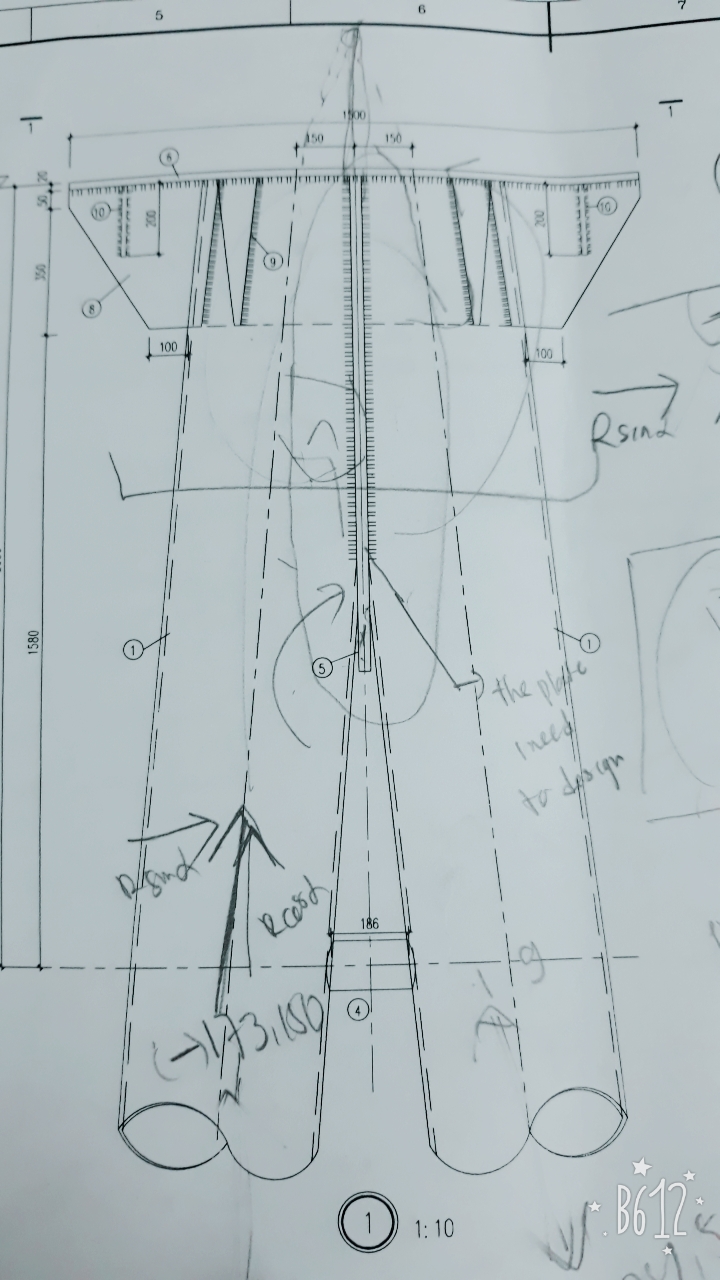
Assalamualaikum, Im designing a connection a pipe to pipe, between this pipe i have to add a plate to connect the pipe with welds. How can i determine the thickness of the pipe? Do i just design it based on tension load on the pipe? Cause my senior said that theres an eccentricity and i have to design it to resist such loads, but im not sure. Heres the figure of the drawing. Regards Groszni
-
BEAM COLUMN CONNECTION LIMIT STATES
groszni awesome replied to groszni awesome's topic in Steel Design
do you calculate the dimension of the stiffner as a tension member by using these load-> required load for stiffener = force load by beam flage - column web resistance ? -
BEAM COLUMN CONNECTION LIMIT STATES
groszni awesome replied to groszni awesome's topic in Steel Design
but i didnt use an end plate connection, the flange of the beam got welded to the flange of column, and the web of the column connects by double vertical connection plate attached/welded to column (fin plate i guess). -
Assalamualaikum, im designing beam to column connection, i wanted to know what are some limit states on the beam and also on the column? and also i need a correction in my design, heres what i did : 1. designed the top and down flange groove weld to resist tension caused by Mu, Tu=Mu/(h-1/2tf.2) 2. designed amount of bolts on the web based on shear force 3. designed the connection plate on the web based on the shear force / axial (tension force) on the beam. 4. designed the fillet weld based on shear force acting on the beam what else i have to check/design? thank you regards.

-
Check the one way shear and two way shear to determine the thickness, you could do the slope thickness variation btw (thicker near the column).
-
What are some ways to reduce lateral displacement of column, In case i couldnt add lateral bracing to my building and have already got the column orientation in right position(column axis to resist force)?
-
steel design - segui
-
doesnt work like that, you gotta check the compression steels strain (ecs) , it usually dont yield so you couldnt use fy
-
thank you, would you mind if i ask you to draw the mechanism? thanks.
-
How do we design flange brace to resist LTB on structural steel beam? Whats the mandatory force to design it?
-
RSA would do it, there are so much parameters u gotta assumed/determine in time history analysis, plus you dont have that lot of seismic acceleration records in indonesia
-
do it as usual way, take the base moment and the axial load from the column
-
shear modulus and shear wave velocity of soil
groszni awesome replied to Hanii's topic in Foundation Design
so is it possible to just using SPT to determine the soil site classification on earthquake provision? as u said that we could do some calculation empirical formula to convert the SPT to Vs maybe? -
foundation design by Bowles or Braja M.Das
-
this only works for gravity loads though