

aka
-
Posts
10 -
Joined
-
Last visited
aka's Achievements
")
Newbie (1/14)
0
Reputation
-
yes i have like opted for atleast 3 inch or use of epoxy and my contractor thinks use of epoxy is a waste of money because the building is residential,and the construction is being paused after 10 years of its erection.And i want to ensure the joint should not be the reason of the concrete connection failure as such. Thankyou sir,i really appreciate your fast reply
-
 aka reacted to a post in a topic:
Existing Rcc column to New Rcc column connection
aka reacted to a post in a topic:
Existing Rcc column to New Rcc column connection
-
hello,I want to know how deep we have to go in the existing column by scratching off the layers of old concrete,to provide a bond for new rc column?Is there any minimum depth mentioned in any codes? like suppose the lapping should be 60 times Ld generally.Please help,my contractor is telling he would go 1 inch by digging 1 inch hole in the old concrete and i don't know if it is sufficient or not.
-
please provide me with elcentro 1940 response spectrum
-
Hello can anyone please provide me with Elcentro response spectrum?I just could find the time history curve ..Please provide
-
Attached is a thin plate stress distribution done in SAP2000.The units are KN-m.E value is 210GPA ,and the area section so choosen is shell thin with plate thickness t=20 mm, the thin plate is idealized into two triangular element with a 'None' element to connect two area elements at the diagonals. Along x axis is 400 mm and y axis is 200 mm.The manual calculation matches exactly for the displacement at nodes.However,the shell stress is not matching .As per manual calculation ,the sigma x and sigma z are coming out to be 6964.53 KPa and -7.53 KPa respectively. However in Sap2000, sigma x or S11 is about 6859.44 Kpa,while S22 is about 990.34 KPa and S12 or Txz is about -97 KPa from the calculation whereas from manual calculation it is -16.1 KPa???why is it that ,is it because it is not meshed or so? Please spread some lights on shell stress and my understanding on it .I have attached here the stress contours and displacements. stress.docx
-
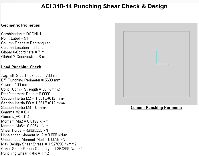
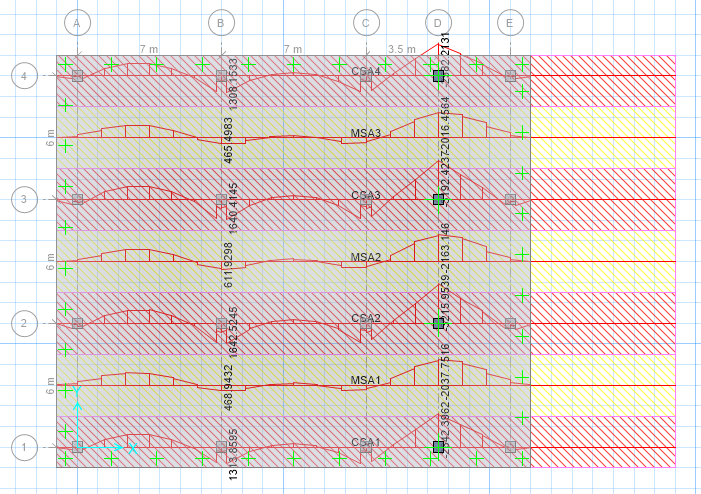
Hi, I was modeling a not so regular mat footing in SAFE software.The position of column was changed accordingly per grid but the main problem was when the design strips moment was checked along x direction,the following problem occured as shown in figure because previously the grid was maintained to the standard template.I went to Interactive data editing,but couldnt figure out the actual problem,Please help me how do I actually get this solved?Another problem was when I went to Design tool and changed punched shear overwrites for interior column different behavior or edge column behavior,I was not able to retrieve the same value as from the manual calculation.Another though on it was ,Is defining subgrade modulus of soil necessary ?what to do if only bearing stress is mentioned in the question.Please go through the attached figures herewith.Thankyou ,sep

-
There are two three columns in a grid ,two are placed in the same line another is to the downward side of the two columns,The two collinear columns are at 5 m apart and the next column is at 1.5 m apart tentatively.What the engineer has done is,tie the two collinear columns with strap beam,because the edge is on the property line and moreover at a large distance apart and the interior column is combined with the downward column (the downward column is at property line too).Is it possible to use combined footing and strap footing at the same time?My concern is ,the engineer has not separated out two designs for the combined behavior of the footing ,he has designed it as separate,one is strap footing ,the other is combined. Is it because ,the pressure intensity disperses over large area ,so he has taken it as single behavior?Wont there be site difficulty during casting?And is the design ok??I have attached the file herewith.

-
Hello.Please suggest me some good books on timber and its component design?and if possible,the functionality of its to design in software?
-
@EngrUzair sir but the page is not found .
-
Hello, I came to know that moment redistribution is possible in software(ie ETabs,SAP),but for this we need to know the plastic hinge or rotation capacity of that element?Is it possible to directly know the rotation capacity through software or is it handdriven and later the moments are redistributed?I would like to know how we can model and redistribute the moments through software.Thankyou