SALMAN CH
-
Posts
20 -
Joined
-
Last visited
-
Days Won
5
Content Type
Profiles
Forums
Events
Everything posted by SALMAN CH
-
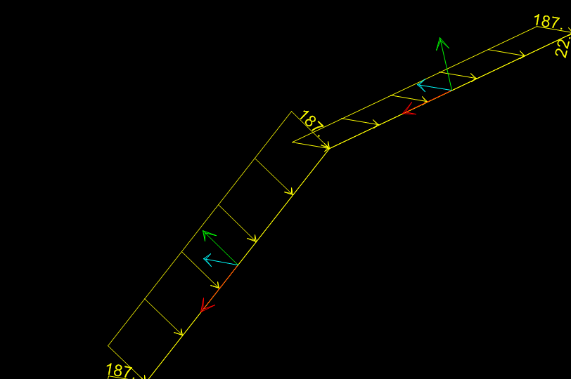
@Hira Malik.. Actually i cant see clearly in pic, only model can tell me right, but this seems to be wrong direction, this load should be applied in 2-2 local axis of frame, what you applied is in longitudinal direction not lateral load. See the loading i attached,axis 1 is in red,3 is in cyan and 2 is in green, your pressure will act in 2-2. In one element i have applied loading in 3-3 which is lonngitudinal and in other element i have applied in 2-2 which is right direction. If you will draw a tangent this circle, you will see on every point, the lateral pressure will be like at right angle so for this cross sectional 2 d frame,2-2 is the right direction. Even if you will draw a curve on CAD and import it SAP2000 will divide it into series of linear elements, you can not just select one and assign it once. For more precise analysis you can further divide these segment. Read this: https://wiki.csiamerica.com/display/kb/Curved+frame+objects
-
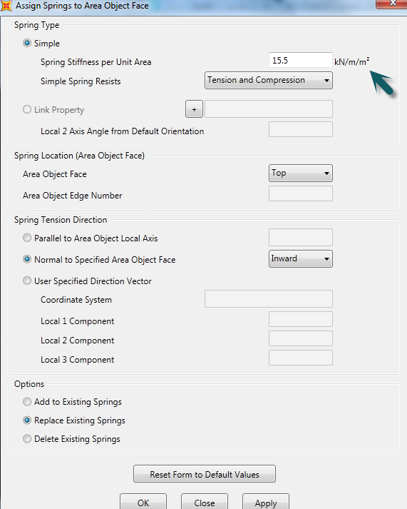
@Hira Malik.. Please see following response for your questions Q1. Soil spring stiffness for normal rectangular mat/raft is taken as : For area spring, : from mod of subgrade reaction which is generally taken as K = 90xB.C for raft. (Kn/m2/m) For Joint springs, If you are applying joint springs, you have to multiply it with equiv tributary of that joint.(Kn/m2 xm2= Kn/m/m) For Frame springs: multiply the value of K with width of frame element, and if the spacing of frames are different than 1m, also multiply with spacing 2. Generally, the triangular loading is applied via joint pattern for shell elements. Would you please tell us you are modelling it as a pipe, shell or a 2d frame element. I can explain you better, if i know what are you doing. You can also apply varying load on frame element, go to distributed load you can give value of loading after each distance rather than equally distributed. 3. It is very easy to apply this circular circumferential loading e.g for frame element, first turn on the local axis of the element, go to distributed load while applying load change the axis from global to local, it may be in local axis 3 of the frame element. @Gossetto.. you can also apply nonlinear soil properties by using link element, in-spite of linear link, select Gap link element.see this https://wiki.csiamerica.com/display/kb/Pile+lateral+support+based+on+P-y+curves
-
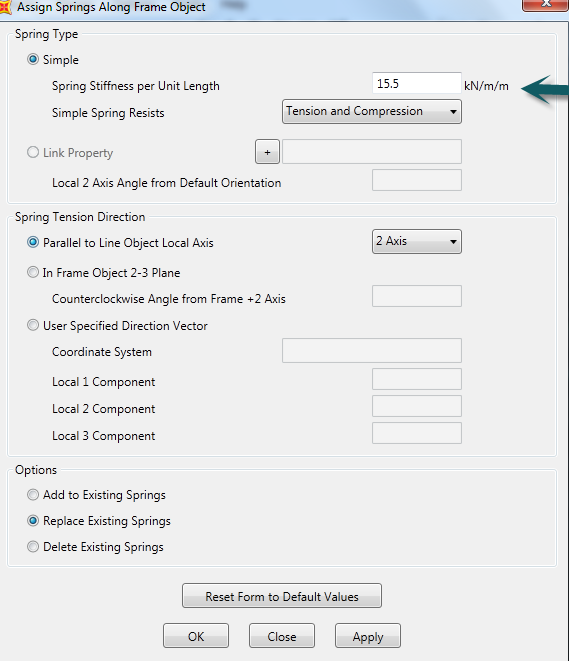
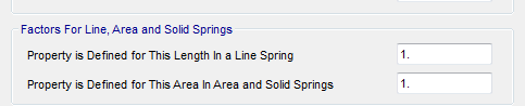
@Hira Malik @UmarMakhzumiFrom picture attached, he probably wants to model the behavior of soil around your structure means soil-structure interaction using a link element. You can use Line springs to your frame elements in-spite of Link elements. As far as property of link element is concerned, it might be easier for you to explain in line with normal bridge modeling, many bridge designers uses link elements to model neoprene bearings in-spite of hinge condition. You can specify actual stiffness of the bearing in flexure and shear. This guy is using "mm units". 1000 and 1000000 is nothing simply factors to convert this to "m" like you define the properties of Line springs and area springs for any element frame and shell elements to model your soil interaction. Please see the image below. Factors 1m = 1000 mm, 1m2 = 1000000 mm2. If you will use units as "m", you should put 1 and 1 in both factors, like attached below. See last picture whereby a bearing is being modelled using a link element.

-
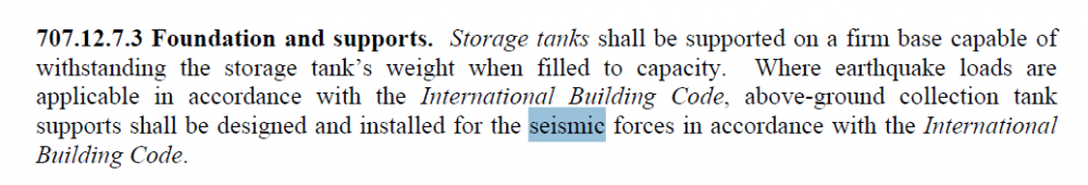
@UmarMakhzumi..The base line of this code is "International Energy Conservation Code", so does the primary objective of this code is effective conservation of energy in buildings and promote green construction environment rather than structural design. it was supported by ASTM and ICC. Wherever seismic design is concerned it directs to International building Code ( IBC ), so no change in probability of seismic activity. In one of my project client asked about the building span/life, so we recommended him 50 years based on what you asked and past experience, however architect recommended 60 years. Thanx
-
@UmarMakhzumi just want to add one cent, in gulf region, some companies are also focusing on IGCC for sustainable and Green building concept, when client inquire about the Life span of building, specially Architects refer to IGCC(International Green Construction Code).

-
@ZOHAIB SATTAR NAGRA.. Habibi for sure i know the concept i only want to tell you this point is not valid for IBC. Kindly read the discussion in the forum. http://www.sepakistan.com/topic/2008-issues-in-etabs-results/#comment-5713
-
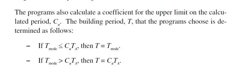
@ZOHAIB SATTAR NAGRA.. Your first paragraph is not clear to me. I feel your confusion is valid point, for UBC code, ETABS takes T=1.4 Ta, If Tmode >1.4 Ta, and CSI manual tell T= Ta, which is contrast to ETABS. However i have checked this problem does not exists for IBC/ASCE provisions. I think you should switch to ASCE, no one uses UBC now.
-
Classification of beam based on height and spans
SALMAN CH replied to groszni awesome's topic in Concrete Design
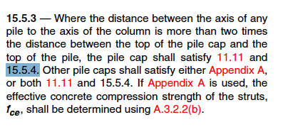
@groszni awesome.. Yes but the idea is you can not analyze your structure based on elastic theory, whereby we assume distribution of strains and stresses which does not remain valid, the behaviour of material changes. For Pile Caps this ratio is 2.5. -
Classification of beam based on height and spans
SALMAN CH replied to groszni awesome's topic in Concrete Design

-
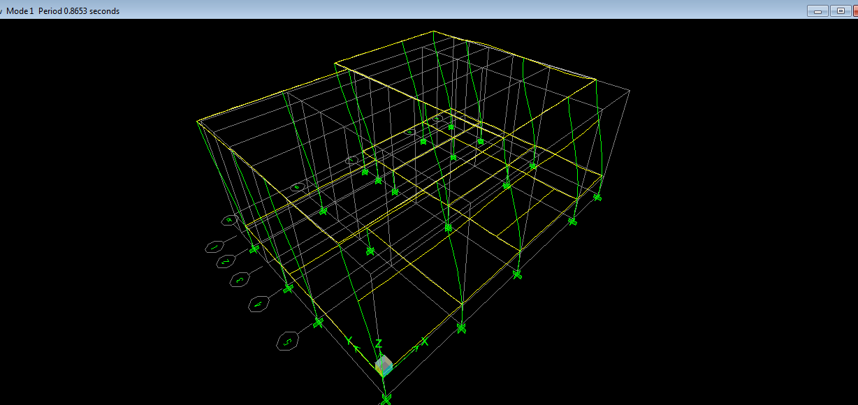
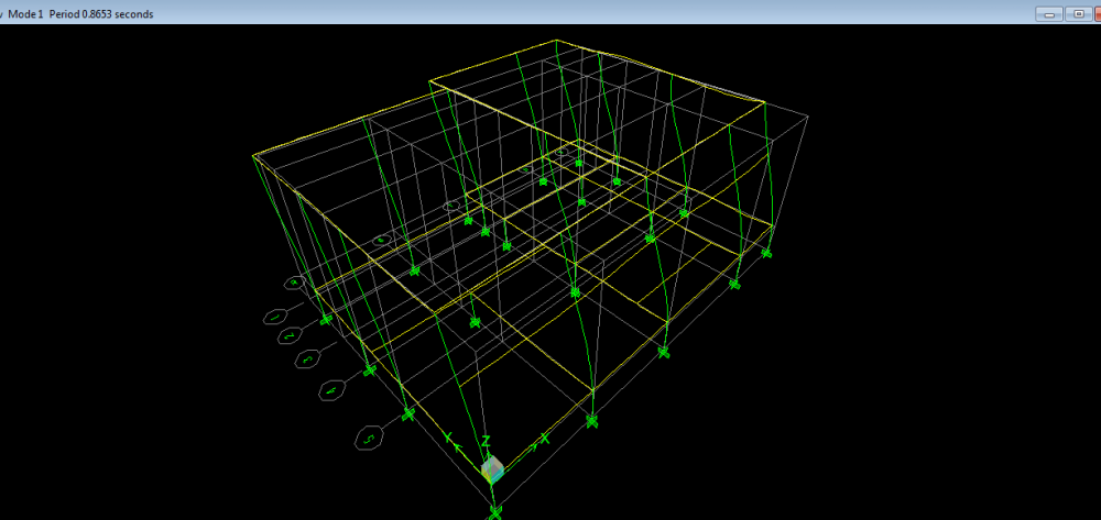
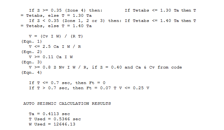
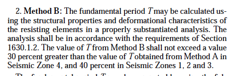
@ZOHAIB SATTAR NAGRA.... Method A is an approximation to find out the time period of the structure without taking into account of structural properties, method B takes into account of structural properties and deformation characteristics. In this regard, ETABS will use the loop of If _ and Else to check the upper limit of Time period, please see the attached summary. For example your building height is z =32.81ft using ct= 0.03, Method A gives Ta = 0.411 sec When Etabs run analysis, it gives T = 0.86 seconds Check the loop in the report of ETABS, because time period of structure can not be more than Tmax, so ETABS will use Tused = 1.3 Ta = 0.411 x 1.3 = 0.534 seconds (For Zone 4) Hope You understand
-
@ali7988 hameed.. I think you want to apply partition wall load on floor slab, for this purpose you can simply draw a null/negligible frame element and apply load over it.
-
@UmarMakhzumi.. @Ayesha...Thank You for your concern. Yes we r on the same page . However my interest was only to highlight the fact that pile cap design is not like slab, due to pile spacing criteria and typical patterns, it will behave like a deep beam in almost every structure. However i feel there is no proper technical inputs on this component of structure and engineers follows whatever practices are in their offices. In this regard i would like to add little knowledge as per my experience , that unlike the normal slab, the critical sections for maximum FORCES will also be changed , it needs 5 to 6 special investigation as per the reference handbook mentioned in commentary of ACI. Regards
- 10 replies
-
- 4
-

-
- sefp consistent design
- piles
- (and 1 more)
-
Assigning Of Temperature Load In Etabs And Safe
SALMAN CH replied to Aadelaadel Fd's topic in Software Issues
@ZOHAIB SATTAR NAGRA.. Applying temperature to vertical elements (Wall) will hardly effect your design, this is my observation. "It is pertinent to mention that biggest trouble for frames/walls will arise due to the application of temperature loading on slab area". -
Assigning Of Temperature Load In Etabs And Safe
SALMAN CH replied to Aadelaadel Fd's topic in Software Issues
@ZOHAIB SATTAR NAGRABefore replying to your question, I would like to clarify that I don’t know the plane of your building, you have big opening whose nature and geometry is unknown to me. Expansion joint might play an important role in your building, if there is abrupt change in the plan, I would recommend to provide expansion joint. In connection to your question, keeping in view the conditions of frame end conditions and heating of the building, briefly, I would like to explain as follows: 1. Intermediate floors will not be exposed to weather conditions; they will be much cooler than roof. Ask yourself what will happen if you will put this load on intermediate floors? Axial tensile or compressive stresses will be developed in your structure. SOLUTION: There will be no loading on intermediate floors at that time, except workers or temporarily loading, the reinforcement you already provided would be sufficient enough to cater theses build up stresses. Nothing will happen to your structure. 2. Your structure will act together, slab will not behave alone; in fact these volumetric changes will occur about Centre of Stiffness. Your frame will try to contract or expand as whole. Connection are not ideal rigid connection, the structure will have some relief from theses axial stress through joints, shrinkage/temperature steel and also through micro cracking which will not be visible.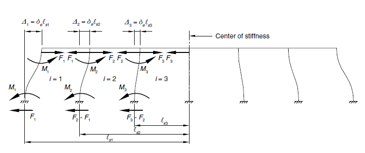
-
Assigning Of Temperature Load In Etabs And Safe
SALMAN CH replied to Aadelaadel Fd's topic in Software Issues
@ZOHAIB SATTAR NAGRA Application of temperature loading and provision of expansion joint depends on engineering judgment of an engineer, keeping in view construction tolerances.What is the length of your building, and how many storey it is? I would like to draw your attention to following comments You can ignore expansion joints till "60m" as per PCA suggestion, however it is not hard n fast criteria.Building Geometry also play an important role in provision of expansion joint. Please refer to ACI Committee report 224.3 Table 1.2. As far as Islamabad is concerned, basically when concrete is poured it generates heat of hydration, your concrete will not be at 5c when it will be poured it ll have some temperature. The structure will not be subjected to difference of 45 degree, it will actually be subjected to difference at the time of casting and mean temperature. Generally we take _+20 C. You can ignore temperature loading on intermediate floor and assign temperature loading to exposed roof surface. Sometimes the assignment of improper temperature loading would attract too much axial load on beams which will not happen in reality.Also concrete will try to relieve it with minor unnoticeable cracks -
Dear Engr @UmarMakhzumi I just want to add something in it, I feel in this quote you wrote”MORE than require by code “by mistake, in simple words when the distance between supporting reactions is less than the twice depth of the member. I would like to add the ACI and AASHTO references in this regard. Thank You

- 10 replies
-
- 2
-
-
- sefp consistent design
- piles
- (and 1 more)
-
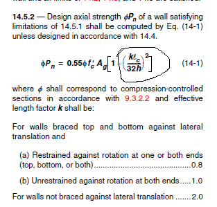
engr @Ayesha there is an Empirical approach in ACI 14.5 which incorporates the slenderness of wall keeping in view the restrained conditions and then calculates its axial capacity. Although you might not agree to use 14.5 due to its limitation, however this is a good rough check. I am cautious about this wall because of the following reason: engr @Fatima Al Zahraa Olleik has mentioned its thickness is 0.4 to 0.25m, I suppose its top thickness is 0.25m and it is varying along the height. How you will support a 4-5 storey building load on a 25cm wall, I don’t know the type of load on building, I don’t know the crushing strength of existing structure; even she should verify bearing strength at the interface of column and wall. A wall with 25cm thickness supporting a high axial load can buckle like a thin column. This is my observation. From the sketch I feel column would be partially supported on raft and partially on wall, this is additional complexity in this project, and column looks like a peanut. I don’t know the seismic category of the building; I am of the view a high base shear may bring additional moment in the wall for which she should carefully verify the capacity of wall.
-
STRUCTURAL DESIGN ENGINEER NEEDED AT A FIRM IN LAHORE
SALMAN CH replied to Hira Malik's topic in General Discussion
Good Morning, I am interested, Kindly check your inbox. Thank You -
@UmarMakhzumi. Dear Engr i would to disagree regarding your statement of design of Pile cap as a typical Slab. Normally pile cap behaves like a Deep Beam action, normal bending/flexural theory is not applicable to Pile Cap design. ACI and AASHTO recommends to use STRUT n Tie model for Pile Cap. However for ease of analysis and design, due to absence of expertise on STM, structural engineers design it the other way. The behaviour of Pile cap supported on Pile follows Bolt Analogy. Furthermore, for modelling in FEM softwares, In Usual analysis of raft slab, you put soil springs under the raft, however for pile cap we ignore effect of soil and pile cap is supported only on piles. Thank You
- 10 replies
-
- 3
-
-
- sefp consistent design
- piles
- (and 1 more)
-
1. I would advise you to check the Buckling of Wall as per ACI bearing wall Buckling Criteria, Since its behavior will be changed from retaining to load bearing, high axial loads may lead it to buckle. 2. Have you checked bearing pressures for wall foundation is it safe? 3. What about differential settlement of the building is it recommended from Geotech engineer. RAFT OVER EXISTING WALL.pdf