Mirza Adeel
-
Posts
5 -
Joined
-
Last visited
Recent Profile Visitors
769 profile views

Mirza Adeel's Achievements
")
Newbie (1/14)
0
Reputation
-
Could you help me understand how moment will be distributed in two ends of beams if one end of beam is fixed and other end is partially fixed? Say, previous 24ft beam with 15k/ft udl....FEM are -720 k-ft both sides.....now one of end has been partially released so that it can develop 360k-ft how will moment be distributed to other end...I am getting 900 k-ft at fully fixed end and shears at 2 ends became 157.5 and 202.5 kips..., I fail understand how to solve this indeterminate beam with one partial fixed end... Thanks for your help
-
Thanks for your reply. Actually your blog was one of the first I studied before doing it. I understood it now. ETABS is using equation like M=(n/(n-1))*4EI/L*theta. so rotational stifness constant k=(n/(n-1))*2EI/L. If you are reducing stiffness on both sides consider using spring constant of (n/(n-1))*2EI/L n=% of moment to be resisted.....for n=1 we will get fully fixed, for n=0 we will get fully hinged. The graph can be considered to be n(Y-Axis) and (n/(1-n))*2 as X axis. The data makes sense now. i am worried about 3D now, I have 55 story building in which i have to model connection loss in terms of decrease of stiffness. I don't know if I could use
-
 Mirza Adeel reacted to a post in a topic:
Rotational spring constants in ETABS
Mirza Adeel reacted to a post in a topic:
Rotational spring constants in ETABS
-
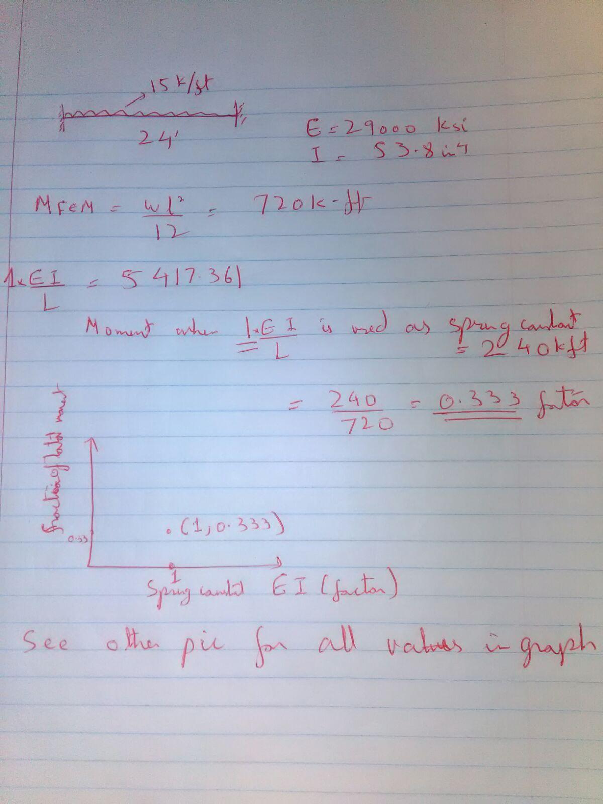
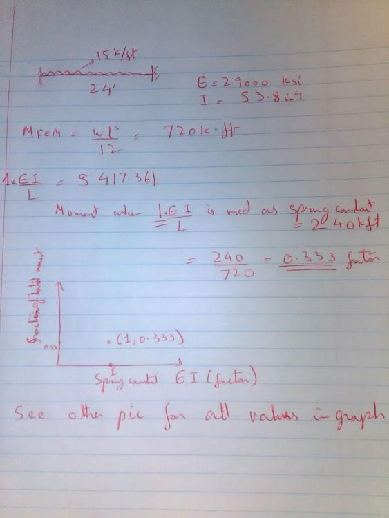
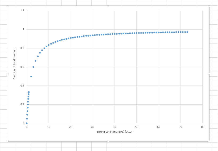
I am trying to understand how rotational spring constants work in ETABS. I have considered 24ft long beam with 15kips udl applied so that fixed end moment is 720k-ft I assume that spring constant will be function of EI/L. I assumed that ETABS would have linear spring, so that if I find lowest spring constant to give me 720k-ft fixed end moment, I would half that spring constant to give me half restain so that moment will be 260k-ft. In reality results are far from it. the graph attached shows factor which I multiplied to (EI/L) to get spring constant in kip-in/rad in X axis and Y axis shows corresponding end moment/720. Can somebody explain how etabs spring constant work so I find factors representing fraction of total restrain.
-
etabs disconnect joint connectivity in Etabs
Mirza Adeel replied to Mirza Adeel's topic in Students Zone
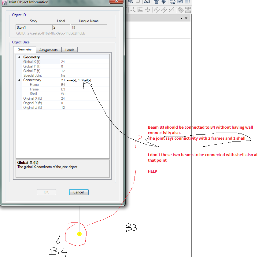
Thank you for replies, This node has to be there. Actually, B3 and B4 are same beam, I have to model this beam at point on wall such that it has joint only at end point and no continuous connection with wall....For that, i have used "no meshing" option for B4 and auto meshing for B3( so that B3 is in continuous interaction with slab) and reason I can't shift the node is that it messes up auto meshing point resulting in unwanted stiffness change from my original model(LONG STORY) In short the node for beam joint must coincide with joint for edge of wall. Also i can't release side of wall although if possible I want to release just that point not whole edge. Is there any feature like in SAP where we can model two crossing beams who just pass like Edit > Edit Points > Disconnect command and it disconnects points then we can connect them as per our requirement like in this example https://wiki.csiamerica.com/display/tutorials/Modeling+a+pin+connection+between+crossing+members Couldn't find anything like this for ETABS. -
At circled point, i don't want beam to be connected to wall, instead it should be connected to another beam as shown without the joint which connects it to wall. The problem is that the joint coincides there....See picture