Search the Community
Showing results for tags 'etabs'.
-
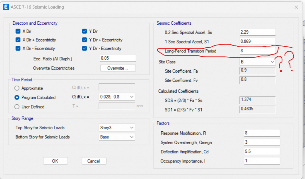
What should i keep in long-period transition period? using BCP 2021
-

Can Any provide guidance on designing a 14-story building in Etabs using flat slabs with a thickness of 30 cm? What checks are necessary for flat plate slab buildings? Also, how can I check the punching shear of slabs at column locations? If you have a re
Zeeshan Ilyas posted a topic in Seismic Design
Can Any provide guidance on designing a 14-story building in Etabs using flat slabs with a thickness of 30 cm? What checks are necessary for flat plate slab buildings? Also, how can I check the punching shear of slabs at column locations? If you have a reference file, please share it with me. -
 I have exported a floor from etabs to SAFE following the correct steps(Analysis+floor only option). However,when I try to analyse the model in SAFE, analysis runs and says complete but there are no results.The lock/unlock model setting remains unlocked even after analysis thus no resultant analytical data to work with.what could be the problem?when I happen to export reactions it just works perfectly. I have attached the F2K and FDB files for considerations FFFourth.F2K FFFourth floor.FDB
 -
Dear Engineers, I have modelled separately two different floors on ETABS and in between is a secondary beam connected to primary beams at the ends. When I pin the secondary beams and do analysis and design,the floors seem to ignore the secondary beams by acting as a single span resulting into longer span with increased deflection and higher reinforcements required.I have attached a file showing this. When I make the joints of the secondary beams fixed,the floors now act as expected;as two separate spans thus giving correct deflection and reinforcement results. I want to keep the pinned secondary beams but again I want the floors to behave normally(maintain separate spans).How do I fix this issue? Kind Regards, Kel

-
I am trying modelling a simply supported plate model in with 10×10 mesh with density 25 Knm2 and E2510^6 and comparing it with results of other finite element applications and also with numerical matrix analysis by hand calculations. Both fem app and hand calculations results match but those of csi bridge and staad pro doesn't though they matched with each other. I was sure of correct modelling and also checked for equilibrium each time, I tried models of other dimensions l b and h as well. Each time fem results and hand calculations matched perfectly. For example I tried modeling 35×50 m plate with 2m depth. Hand and fem calculation results were 30 and 33 mm at centre resp. But csi bridge and staad pro for same parameters gives 230mm. For other models also the result are far too variable like this case only. Please I need urgent support. Any reference would be appreciated. Also how come two fem applications give these absurd results for exact same parameters?
-
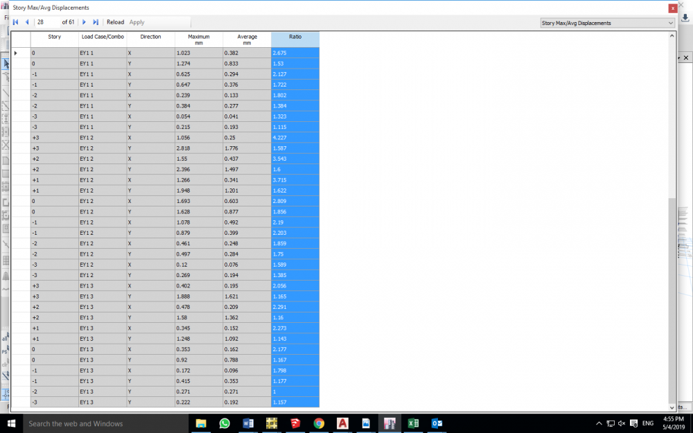
I need to check the torsional irregularity but I can't find the Story Max/Avg Displacements Report

-
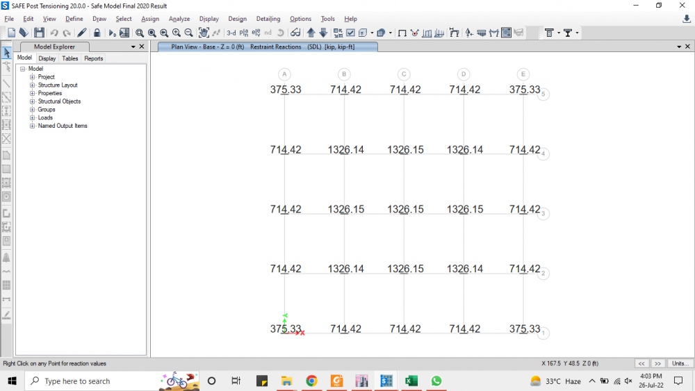
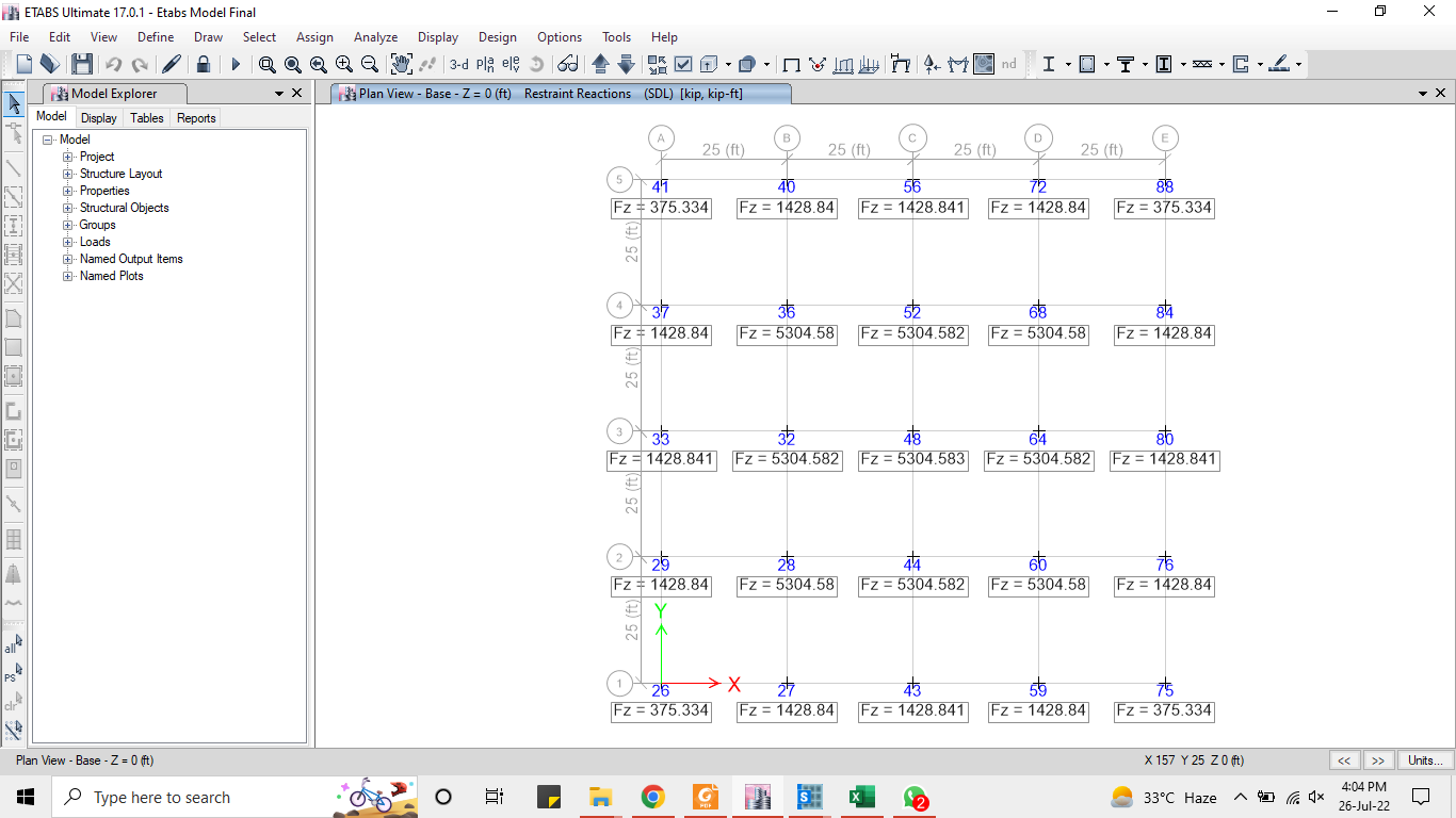
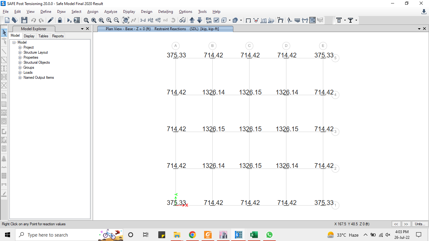
 Greetings Everyone, I am doing a case study for validating the results of ETABS and SAFE using same input data. I am using ETABS 2017v and SAFE 2020v. I have assumed same data to be modeled and analyzed in both software. I have been trying to figure out the difference in my results but no use. I am providing the input data for reference for correction. I have modeled 4 bays (in both x and y directions) with 25' each. Drawn the raft section on grids. I am modeling raft for 10 stories but I will model single story and multiply my loads with 10 for just comparison. RAFT=24"; Slab=6"(for self weight calculation); Modulus of Subgrade reaction=240kip/ft2/ft (Assumed); SDL=90psf; LL=40psf All the loads are factored [(1.2 dead load)+(1.6 live load)] applied as point loads on joints. I have 3 types of joints (Corner, Middle, Edge joints) with their corresponding contributing areas. The loads come to be Corner Joint Loads=410kips; Edge Joint Loads=820kips; Middle Joint Loads=1630kips All loads are assigned under the load pattern of SDL. I have also provided size of load for punching shear X=36"; Y=36". Assigned all raft sections area spring with stated data in direction 3 and compression only. Ran the analysis and displayed base reactions. Results were not matching. I had to explain all the steps so to convey my message properly. KEYPOINT: I am assuming that the inconsistency is coming from the assignment of area springs. Because in ETABS the input data is "Spring Constant/ Unit Area" while in SAFE it is directly defined by the Modulus of subgrade reaction. I even tried to multiply the subgrade modulus with their tributary areas and assigned to their respective areas in ETABS but no use. RESULT VARIATION (Screenshots Attached): The corner joints in both ETABS and SAFE are providing consistent results. The edge joints of ETABS have double base reactions to that of SAFE. The middle joints of ETABS have four times the reactions of SAFE. ANOTHER CLEARIFICATION: I also tried in SAFE v12 and SAFE v16 but I am unable to display the base point reactions in those versions with the same model I was able to display them in Version 20. Thanks and regards, Muhammad Fawad Khan. B.Sc. Civil Engineering UET Peshawar. Etabs Model Final.EDB Safe Model Final 2020 Result.FDB
-
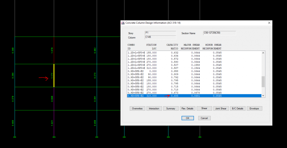
Hello every one I have recently faced a problem in Etabs 2016. after designing a building and displaying: design -> concrete frame design -> display design info -> design output -> column P-M-M interaction ratio I find that in some columns, the ratio that is seen on the column is different from the ratio shown while "right click" on the column (in the table). the difference is so that some times, the ratio shown on the column is more than 1, and while I right click, it shows a number less than 1. I wonder what makes this happens, and which ratio is reliable.

-
Etabs is not showing result for shear design for my shear wall. It writes something in red about number of legs. But the shear design and capacity is all zero. Any help, please?
-
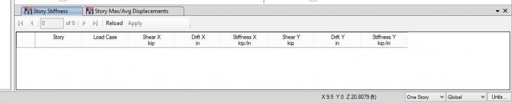
Salam, I have a query regarding finding out the story stifness of building structure. I have modeled a building on Etabs and applied applied UBC Zone-3 lateral loading on it. Ran analysis and then from "show tables" i selected show "story stiffness" and i got a table showing story story stiffness of each story in both (x and y) directions. But when i modeled the same building and applied time history function and selected to show story stiffness from show tables, ETABS is not showing any story stiffness at all. Can anyone explain what is the reason of it?
-
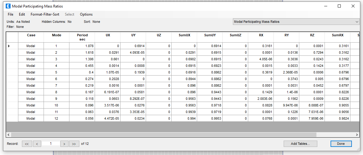
Dear friends, I have building G+2P+7 floors, it's almost symmetric but the second mode is always torsion, I tried many sh. walls configurations but have the same result any tips Thanks I attached the model e2k, G+2p+7.e2k


-
 I am designed A residential house structure in ETABS and now I am stuck in design the footing ... i have watched so many videos on YouTube and attempt to design it but that didn't worked well...... Please guide me the steps for designing Isolate/striped footing after importing the file from etabs to safe. Thank you
 -
I need help on the below mentioned query; My query is dual system design in etabs for 24 story Rcc building. Once the parent etabs model is finalized after all the stabilty checks then we have to find base percentages for both columns and shear walls. And prepare two separate models One for columns and beams design and the other for shear wall design. For these two models where and what we have to modify. If anyone have the reference document for the detailed procedure of dual system design or any reference etabs model Will be grateful for your response
-
Dear members:I was wondering if anyone has gone through this before.ETABS 15, 16 & 18 are all giving me somewhat logical analysis values but wildly false design. Like failure due to buckling for a 20X60 3.2 meters high column in a typical villa. Or requiring a 17000 mm^2 for a column with only 650 KN axial load.It should be noted that this was not the case before.
-
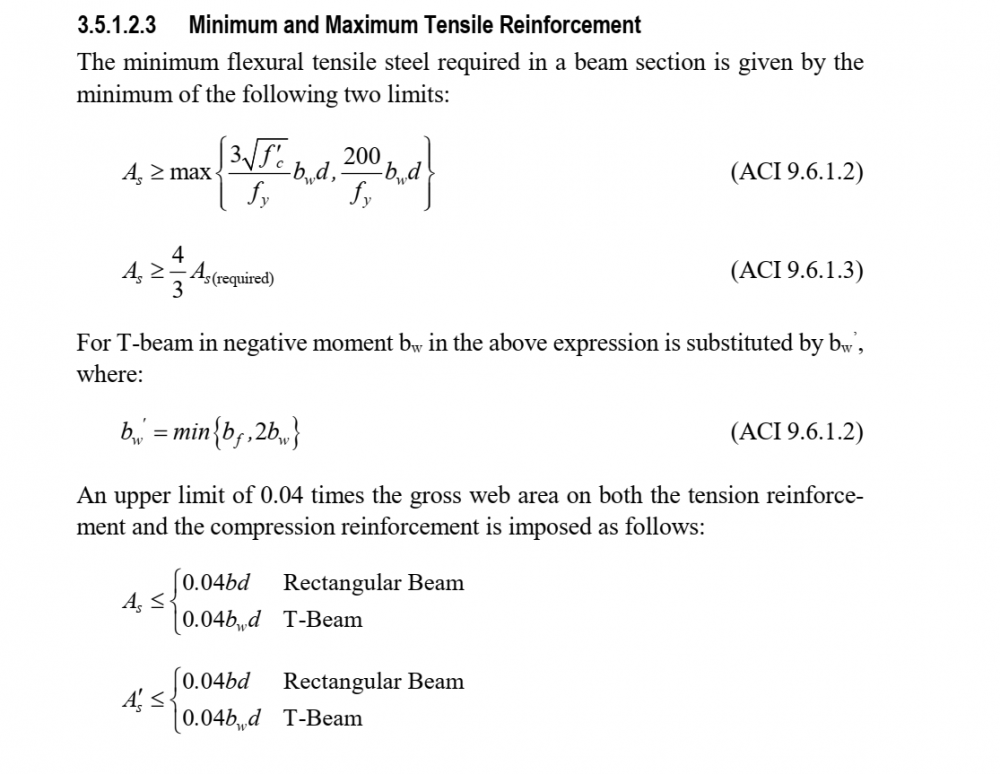
As per Etabs Manual Maximum reinforcement limit for rectangular beam is .04bd. But Couldn't find this limit in ACI Code. Please refer me to the code article.
-
How can we calculate the distributed mass of structure for SDOF?
-
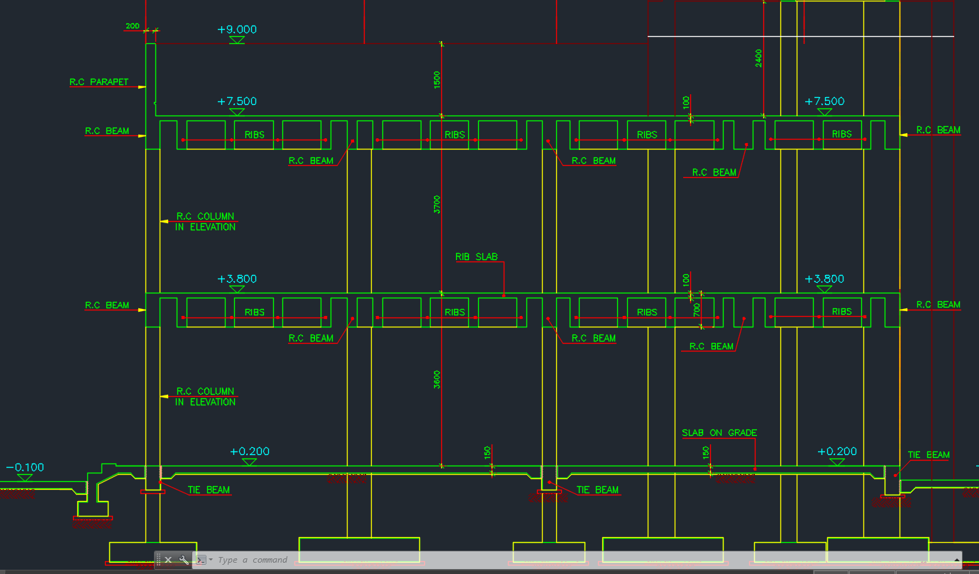
When Calculating external wall load on ground beams (FFL +0.3) Should I take the total wall height on of all stories or just the story above ground beams? by total height I mean (Height of the building to where wall extends (T.O.P +9.00)x thickness of wall in elevation x density (assume 18 kN/m3) ? or take wall height up to (FFL +3.90) x thickness x density ? Please Explain ? Load to be calculated on ground beams!!!

-
Hi all I analysed a G+3 RCC building in ETAB. After analysis and design, i obtained the rebar percentage for each member. for columns, the value of rebar in 3rd story column got higher than the same column in 1st and 2nd story. is it correct..?
-
 Assalamualaikum, My question is basic. Say, i have an eight or ten storied building. Soil condition being good, shallow single footings may be used at a depth say 10 feet below the EGL. If i model the support as a fixed support, and design the footing for both axial loads and bending, also considering the uplift issue, is this realistic for the support to behave like a fixed support in practical?
 -
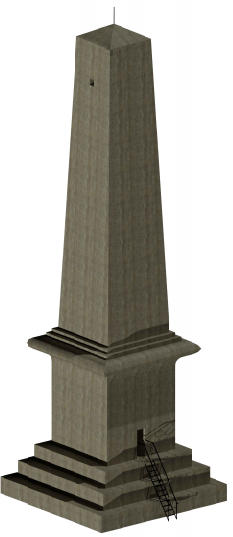
I am working on modelling of "Nicholson's Obelisk" (located in Taxila city) in SAP2000 for identification of its dynamic characteristics and mode shapes as well. This is how structure looks like. This structure is made up of Granite stones only. I haven't modeled a "Solid model" before, I have been trying to model this structure for past few days but have been unable to model it. Problems I am facing are following: 1- In SAP2000 which section property should I use for modelling this structure? Should I consider a wall section or slab section? 2- Should I opt for some other software instead of SAP2000? 3- How can I model the tapering of the structure in software? After getting fed up using SAP2000 for modelling, I tried ETABS for modelling base of the structure but the structure didn't read any object and this is the error displayed But when I modeled the base in SAP2000, this was what I got I have to submit this model by Monday and it's last deadline, so any sort of help regarding modelling of this structure would be highly appreciated. Let me know if you have want more information concerning this structure. Thanks.
-
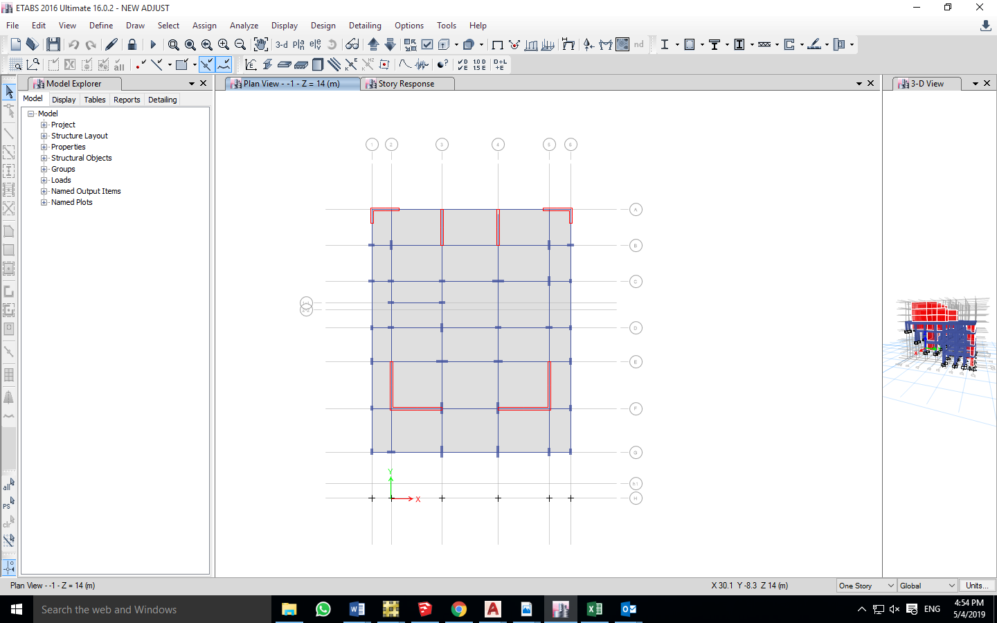
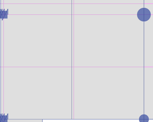
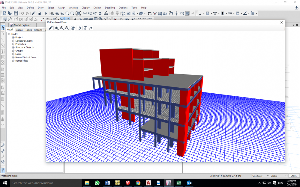
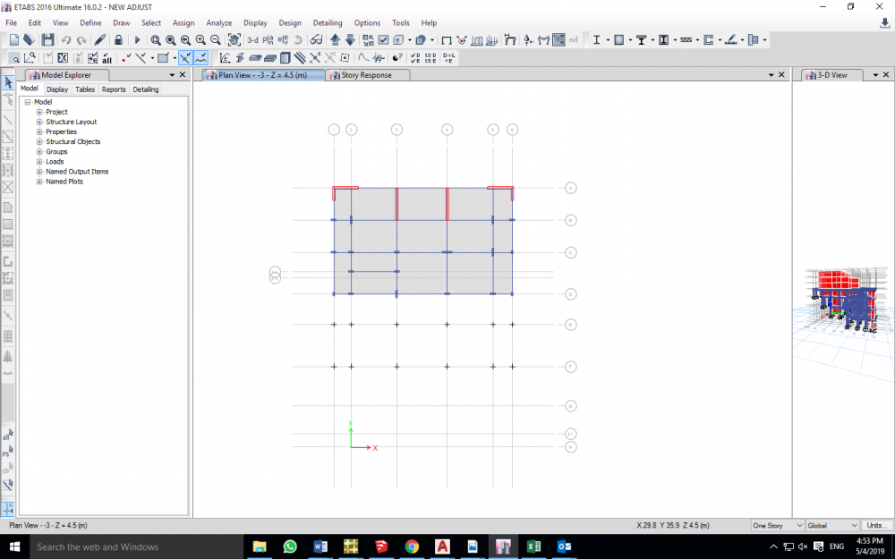
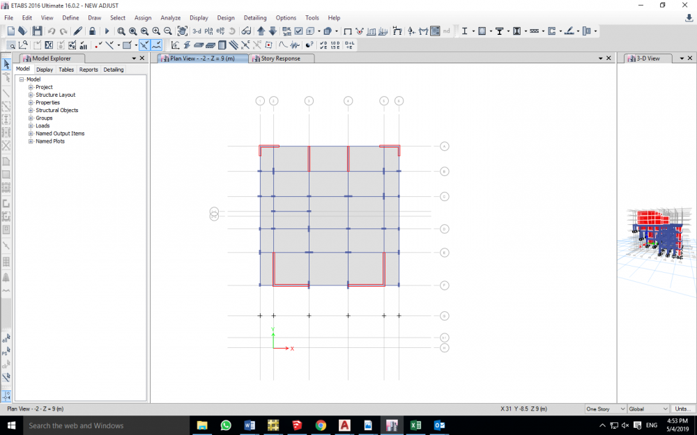
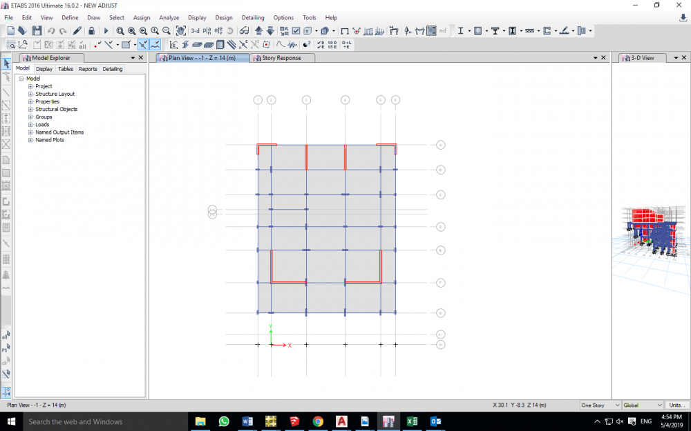
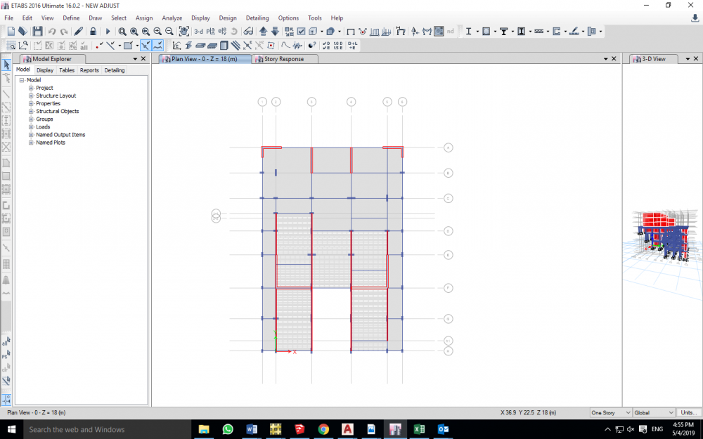
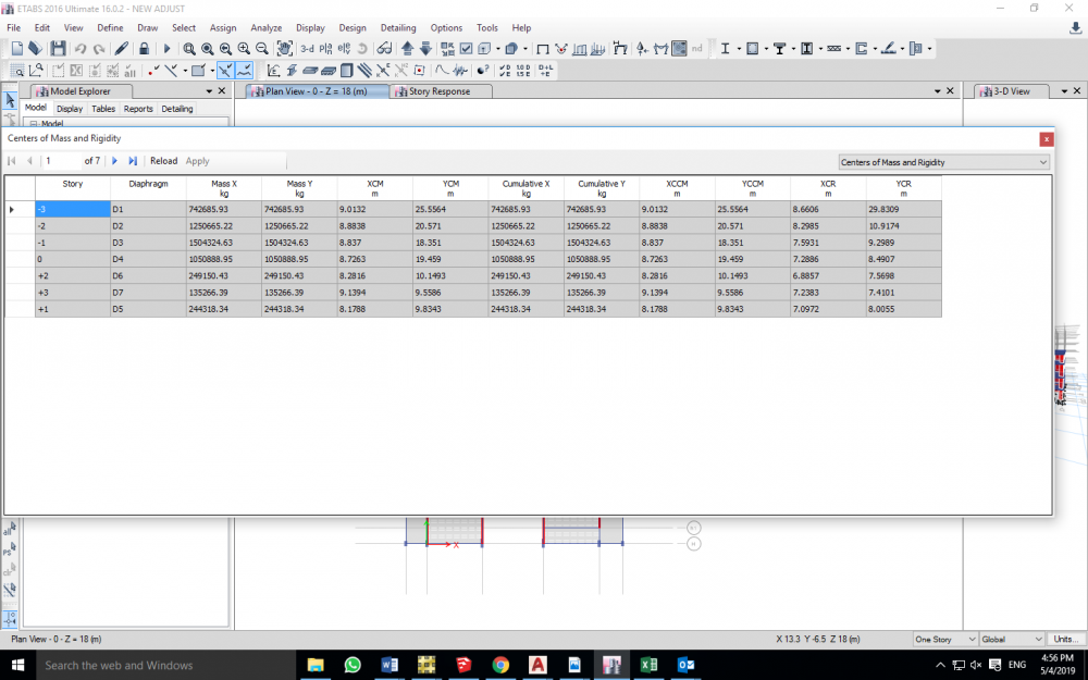
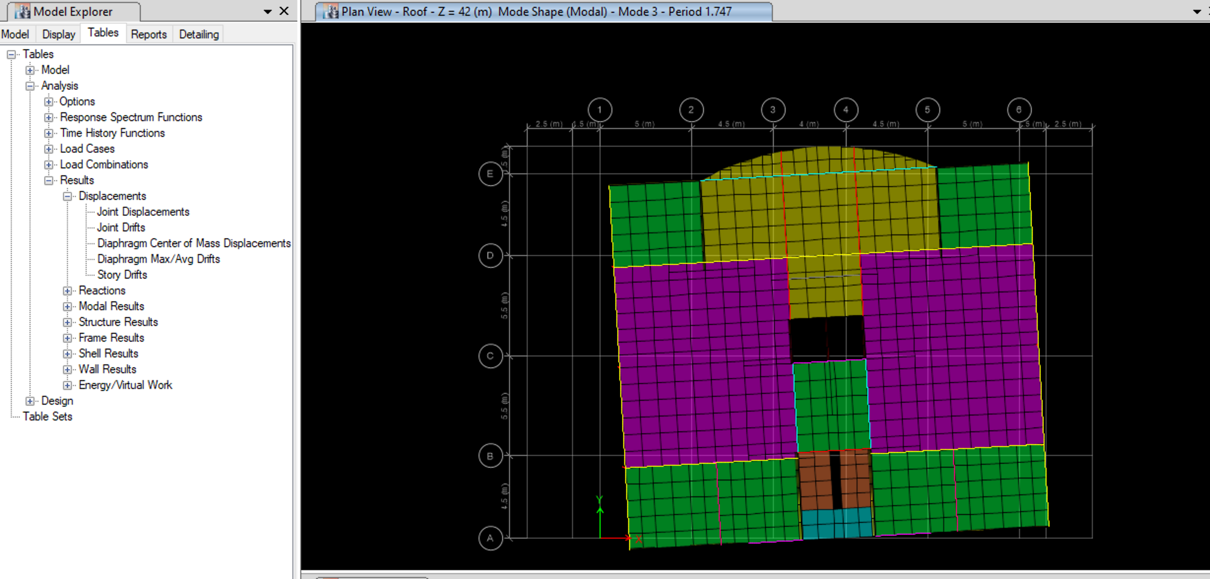
Hello Engineers So I'm having this 7 story building on a sloped land, the occupied levels will be from zero level (Street level) to +3 level , 4 residential stories. the bottom three -3,-2,-1 are being constructed on three levels in order to avoid drilling and any excavation work, considering that building is on hard rock (top of a mountain), and it will be very costly in order to do so. there are many problems that I have Encountered, and I truly need the help from you guys. -the first one is that the occupied stories's structural system is a load bearing walls, rested on Dual system of shear walls and moment resisting frames(the bottom three stories) and now I am Having soft stories , is it correct to model brick walls in the model, as they participate in their stiffness, and if modeled and still there is a soft story, what should I do? as you can see from the figures, the story geometry, specially -3,-2, is way less than that upper floors, and I can't go much deeper downwards in order to increase the number of vertical element. -in the 3 bottom levels+ zero level, Center of mass and center of rigidity are way far from each other, "way more than 5%L", which eventually causes Extreme torsional irregularity, More than 1.4 max drift to avg displacement values are obtained when checked to static load cases, I even Added the two shear walls at the top of the plan on order to pull center of rigidity closer to center of mass, But still, No point of that.I once heard from an Engineer, that Even if the building has torsional irregularity, when you design Piers and columns using Etabs, the program already takes care of that irregularity, as much as I want to believe that, But I think that torsional irregularity is a matter of a hole building geometry and behavior Plus it's a code requirement , and increasing the area of reinforcement won't help, what's right and what's wrong ?-is there any other checks that I should Do ? , is there any recommendations/Suggestions ? **I would truly Appreciate Your help. thank you.
-
Hello Engineers So I'm having this 7 story building on a sloped land, the occupied levels will be from zero level (Street level) to +3 level , 4 residential stories. the bottom three -3,-2,-1 are being constructed on three levels in order to avoid drilling and any excavation work, considering that building is on hard rock (top of a mountain), and it will be very costly in order to do so. there are many problems that I have Encountered, and I truly need the help from you guys. -the first one is that the occupied stories's structural system is a load bearing walls, rested on Dual system of shear walls and moment resisting frames(the bottom three stories) and now I am Having soft stories , is it correct to model brick walls in the model, as they participate in their stiffness, and if modeled and still there is a soft story, what should I do? as you can see from the figures, the story geometry, specially -3,-2, is way less than that upper floors, and I can't go much deeper downwards in order to increase the number of vertical element. -in the 3 bottom levels+ zero level, Center of mass and center of rigidity are way far from each other, "way more than 5%L", which eventually causes Extreme torsional irregularity, More than 1.4 max drift to avg displacement values are obtained when checked to static load cases, I even Added the two shear walls at the top of the plan on order to pull center of rigidity closer to center of mass, But still, No point of that. I once heard from an Engineer, that Even if the building has torsional irregularity, when you design Piers and columns using Etabs, the program already takes care of that irregularity, as much as I want to believe that, But I think that torsional irregularity is a matter of a hole building geometry and behavior Plus it's a code requirement , and increasing the area of reinforcement won't help, what's right and what's wrong ? -is there any other checks that I should Do ? , is there any recommendations/Suggestions ? **I would truly Appreciate Your help. thank you.
-
 May I ask how can I apply the vertical component of earthquake in response spectrum analysis in ETABS with the ACI, UBC, or ASCE code? Also, do I have to apply the redundancy factor for Response Spectrum Analysis?
 -
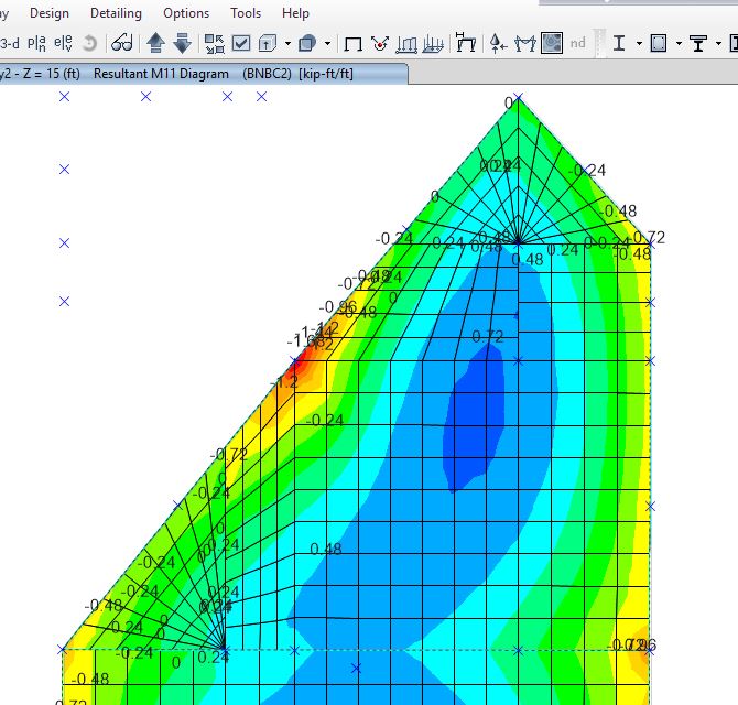
I have modelled a roof of a guard room comprising of folded plates having irregular geometry. For meshing I used Automesh option & further sub-divided it in 12inch size mesh. But, after viewing the results it was evident that the mesh in different panel was not properly connected. Does that effect the results after analyzing? Also how should I assign strips for getting the design of the folded plate from etabs? Please, share a model having folded plates in it & what is the proper way to mesh such elements? The model is attached herewith for your kind perusal. Please fix the model & share it with me. G.R.EDB Guard.Room.EDB

-
Deal All Please suggest according to your experience that which Etabs Version is the Best one in the latest Version starting from Version 9 to version 16 Thanks


.thumb.jpg.51aee45d64f270ded062428cf8d8117e.jpg)