Search the Community
Showing results for tags 'fem'.
Found 13 results
-
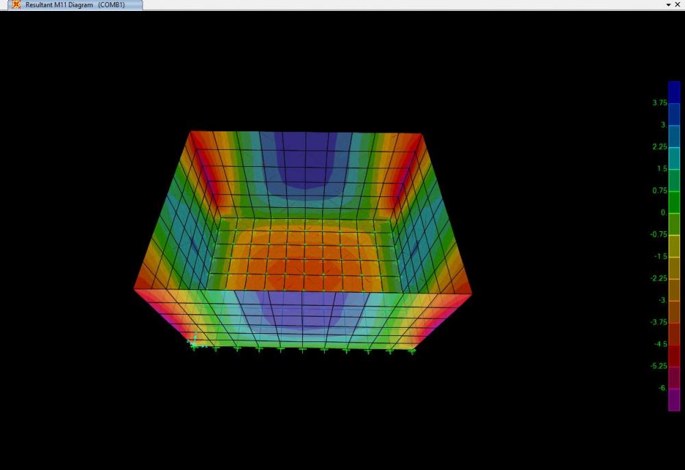
Salam everyone. i am a bit confused about the M11 and M22 in ETABS and how to provide reinforcement for these in a one-way slab or a wall. kindly see the attached pics and guide me that for this M11 moment, r/f will be provided in what direction and why?
-
Hey there, I wana know whats the size of frame object auto internal meshing into discrete elements in CSI softwares (Etab, Sap) and how can i see it in my program to verify it, (extrude view is helpful as per i have tried it ). Any reference where they are mentioning it , I have gone through analysis manual but couldn't find it there , or may be i have missed. Please comment your views.
-
 I am designing a 10 storied industrial building . Architect used a slanted wall in the front elevation of the building for aesthetic reason. But for structural framing I need to model this shear wall in ETABS. Is is possible in ETABS or I have to use any other software?
- 6 replies
-
- 1
-

-
- modelling
- building design
- (and 6 more)
-
Asalamaliekum Firstly i am not sure in which group i should start this topic but the admin wishes he can move this post to the appropriate group. The topic title is one of my subject in M,Sc Civil Engg but i am unable to find any appropriate literature on it. Below are the topic i am interested in if anyone has the related literature please share them. · Concept of structural stresses based on linear finite element method (FEM) · Static assessment based on non-linear FEM · Fatigue assessment based on stress and strain calculations · Fracture mechanics to determine crack growth Looking forward to hear from the experts. Kind Regards, M. Omer Anwaar
-
Anyone can explain what is smeared crack models? Fixed or rotating models? I have searched on google but I couldn't understand what exactly they mean. If any one can explain in simple way or refer any book which can help me understand the cracking models and their behavior. Thank you
-
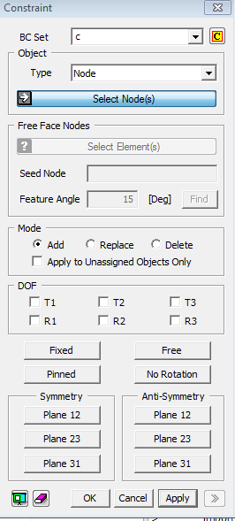
 I have to model a simply supported beam using finite element modelling. What support conditions should I put for roller and hinge? Attached is the picture of software options for constraints and also the beam which I modeled as Simply Supported *If I make a cantilever beam with fixed support, Solid beam gives correct result of stresses. But I think that I am doing something wrong when making 3D solid simply supported beam.
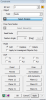
-
 What would be the proper choice between shell and frame for modelling 1.2m x 0.6m vertical element? In a building I am studying expansion joints. All columns are 600mm dia circular. Except some vertical elements 1200x600mm. 1) The question is what system for seismic behaviour you would consider as per ASCE? shear wall or frame? 2) How would you model 1200x600 as frame or as shell?
 -
What is the difference between stress at integration point and stress at nodes? Which one is better to use? Thankyou
-
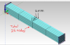
I have read the description in previous forums about shell, membrane and plate in Etabs. (Thanks for the great info) When using finite element software, to make a beam, we can use line element(1D so 1D stresses), plate element(2D so give 2D stresses) or solid element(3D give 3D stresses). when analyzing the beam using all these 3 elements, the result of deflection is different. why? how do we know whether to use 3D solid element for beam or 1D line element for beam? Manual results matches when I use line elements as a beam.
-
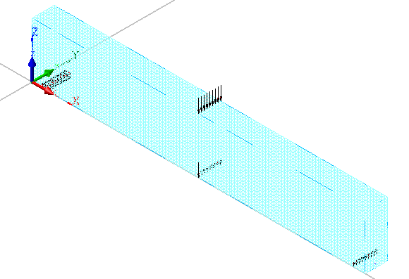
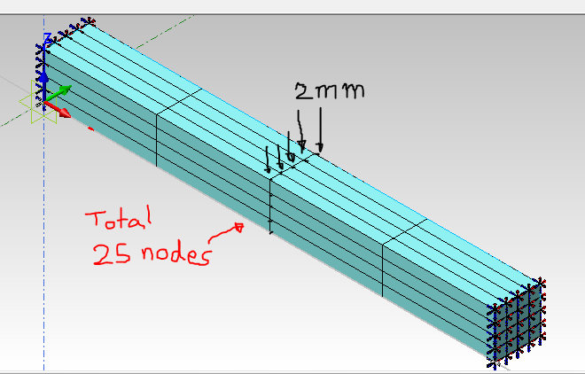
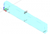
How to assign the displacement in the centre of 3D solid beam? If i have to put 2mm displacement and at centre i have 25nodes so should i put at centre node the displacement value or should i put the displacement value on all nodes?? e.g for load of 25N, I divide it to 25 nodes and assign each node 1N load. Should I do the same for displacement? *Attach is the picture of beam
-
For nonlinear analysis it gives the error: "too small step in Automa. Check your model and decrease minsiz if it is correct" i have change the minimum size step from 0.001 to 0.000001. but there is no change. It still shows the same error and result is generated for the load i.e 306KN. But the applied load is 500KN
-
DEAR ALL; WHAT IS THE ACCEPTABLE MAXIMUM MESH SIZE IN 1. MAT. 2. SINGLE,COMBINED AND WALLS ETC...
-
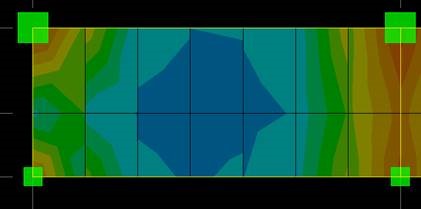
I have to submit this week my assignment for finite element analaysis course. I have to make a FEM model for a deep beam with different support conditions and then verify. I want to know what are different verification methods i could use, and how? I mean how can I knw the non-linear distribution of stress and strain of deep beams, like in shallow beams it was Stress= My/I. Any suggestion for FEM model? I will be using LUSAS program. ( I dont know if the material is concrete...so dont want to use ACI theories..i just have E and other data)