Search the Community
Showing results for tags 'insertion point'.
Found 5 results
-
Salam everyone. Does anyone know if you can modify insertion points for shell elements in SAP 2000? Regards, Haider Ali
-
I placed some columns or shear walls using insertion point to be in the edge of the building but when I want to see the extruded view of 3D or plan the location of the columns and shear walls appear in the opposite location how can I fix that and this issue can affect the analysis of the model another question: How the insertion point of the members affect the analysis results


-
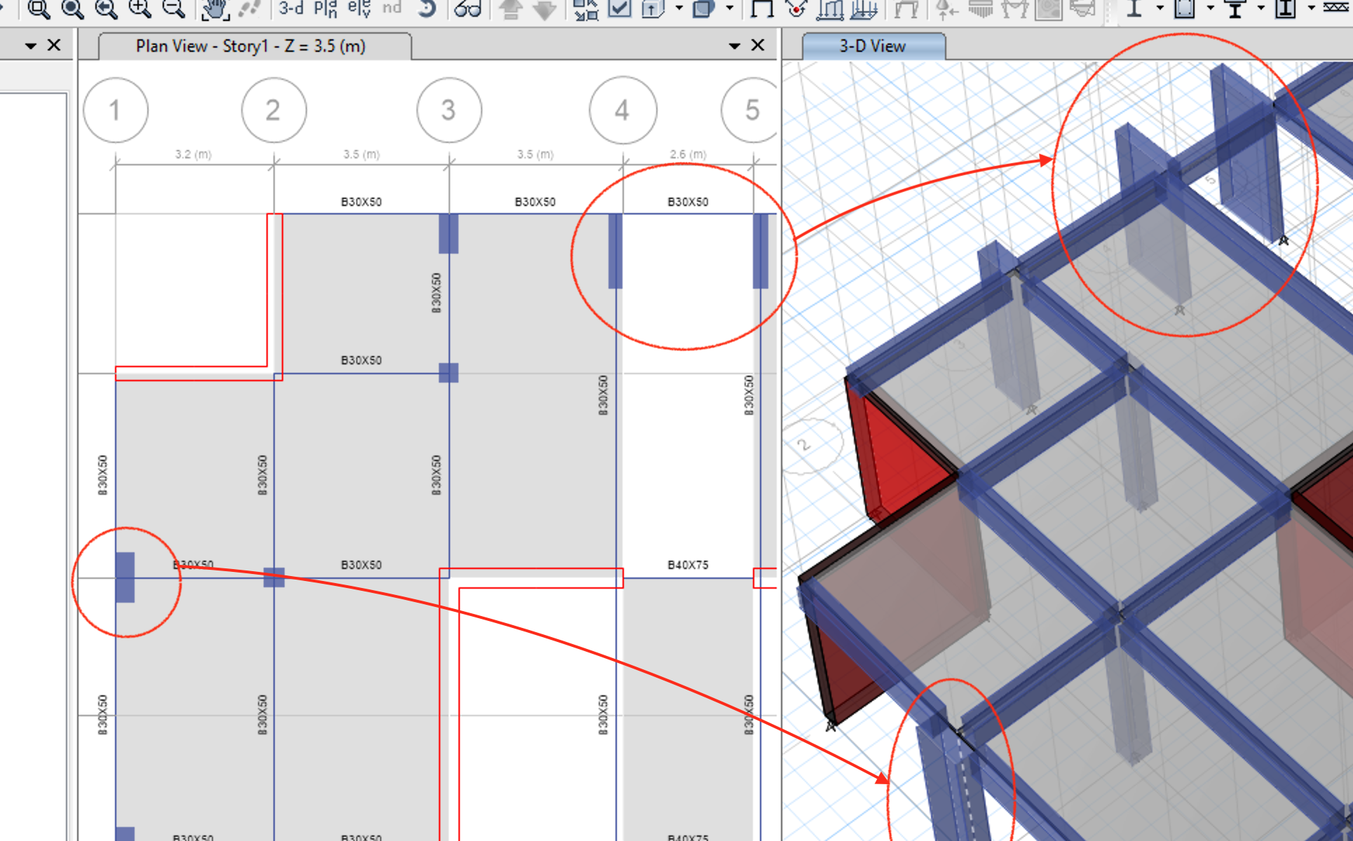
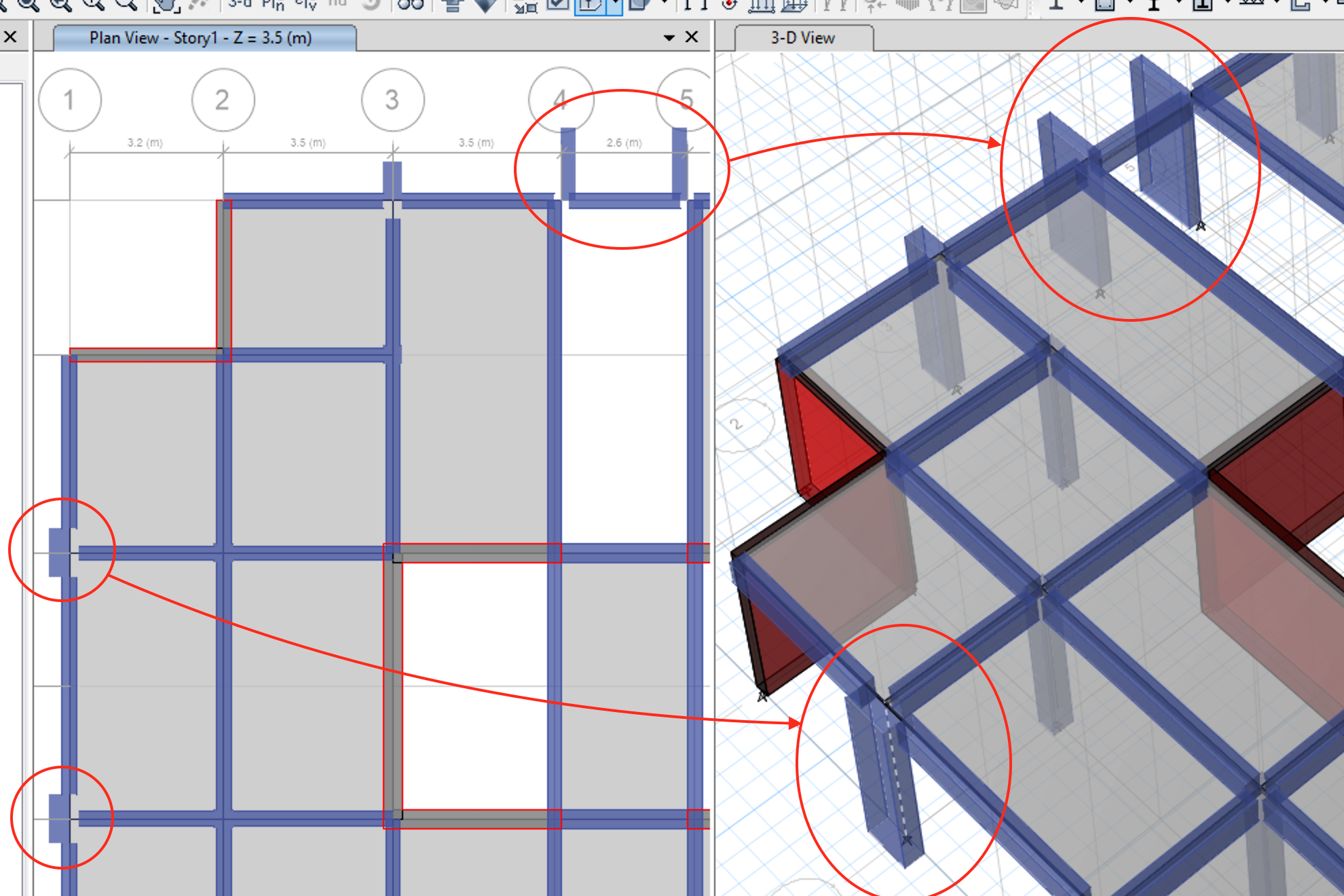
Assalaam o Alliakum Everyone, I made a model in ETABs but it had beams joined at centroid of columns as shown in the pictures below. That was not the case in architectural plan. In architectural plan many beams are at edge of columns. So I used insertion point option to offset all the columns (manual offsetting causes problem in load transfer). I unchecked the "Do not transfer frame stiffness for offsets from centroid" box. But when I extrude the frame some beams became distant from column (in the the extrude frame view only) and other penetrated the column. I then used end length offset option to adjust the beams result was this: Is the method explained right or wrong? Because I did not apply rigid links. Should I provide rigid links? Does the use of insertion point mitigate use of rigid links between columns and beams? Which one is more conservative or preferable while modelling, one with beams joined at column centroids or the one with beams at edge? Which method do you people use?
.thumb.png.0d5973926dc5a9b98c1a3fa13df732eb.png)
.thumb.png.9df5b37b5dea8758d7004d9f057dfddd.png)
.thumb.png.609603255fa3ea7b63ba04a5f53b3ee2.png)
.thumb.png.262c2940d4d2f66e0189cf386215a852.png)
.thumb.png.b083edec205801095f21a327de6f8466.png)
-
 in default condition the beam will lies at the centroid of beam and will not take any force but when we apply insertion point to fame the rebars in frame/beam significantly reduced due to reduction in moments and these moments converted into axial force in beams. is it correct way to use this feature. please guide.
 -
Hello everyone. I would like to model eccentricity of columns and beam but I have encountered some problems using the insertion point in Etabs. Here are my questions: 1. What is the difference between using cardinal point and joint offset? I tried to joint offset a column as if it was offset using the cardinal point (eg. bottom left), but then the analyze results are different. Why? 2. When using the insertion point, we have to transform the stiffness. I did not do any offset but changed the transform stiffness option to "yes" then applied a point load at the top. Comparing to columns without stiffness transform, the results are different. Would anybody explain why? And when we use the insertion point, shall we transform the stiffness of the object with offset? Or shall we transform the stiffness of objects which have connection with the offset object as well? Appreciate!
- 1 reply
-
- 1
-

-
- Offsets
- transform stiffness
- (and 3 more)


.png.cfb8c921ed74f7d454946667fe4837d1.png)
.png.3050509819b02446783427a7a0a77dee.png)
.png.1ed20db0852743a725e55318ca08c807.png)
.png.0c13ee00a4dd2f46f91f0962807976e3.png)
.png.44a1098b236758765f79848732a3d571.png)
