Search the Community
Showing results for tags 'sefp consistent design'.
Found 9 results
-
*SEFP Consistent Design**Pile Design**Doc No: 10-00-CD-0005**Date: Nov 21, 2017* This article is intended to cover design of piles using Ultimate Limit State (ULS) method. The use of ULS method is fairly new for geotechnical design (last decade). The method is being used in multiple countries now (Canada, Australia etc). The following items shall be discussed: Overview Geotechnical Design of Piles (Compression Loads, Tension Loads and Lateral Loads) Structural Design of Piles (Covering both Concrete and Steel) Connection of Pile with the foundation (Covering both Concrete and Steel) Pile Group Settlement Things to consider 1. Overview Piles provide a suitable load path to transfer super-structure loads to foundation where shallow foundation are not suitable - this can be due to a number of reasons like existing space constraints or suitable soil strata is not present immediately below structure. Other uses can be to meet design requirements like to have reduced settlement etc. This article shall cover the use of straight shaft cast-in-place concrete piles and straight shaft driven steel pipe piles. There are a number of additional piles types like belled concrete piles, precast concrete piles, screw / helical steel piles etc but the discussion to choose a suitable pile type is not in the intended scope of this article. The article is intended to discuss design requirements for straight shaft piles only (both concrete and steel) . The aforementioned topic about pile selection is a very diverse subject and requires a separate discussion on its own. Before I get into the nitty and gritty of pile design, it is important to highlight that as a structural engineer working on pile design, there are a number of parameters that you would require from the geotechnical engineer. Generally, these parameters are provided in the project geotechnical report. Based on those parameters, the geotechnical design of piles is performed first followed by structural design of pile. The next section talks about the geotechnical design of piles. 2. Geotechnical Design of Piles. Geotechnical design of pile means sizing of pile. This includes determining the following two geometric properties of piles: 1) Diameter or radius 2) Length Straight shaft piles embeded in soil derive their capacity from two sources. The first one is the skin friction along the pile length and the second one is the end bearing. In order to complete the geotechnical design of piles or in simple words to "size up the piles", you will need skin friction values for different soil strata through which the pile would penetrate or lie and the bearing capacity of the layer in which pile would terminate. This information is provided by the geotechnical engineer in the project geotechnical report. Generally, they would provide a table showing skin friction values of each soil layer for both tensile and compressive loads along with end bearing values of each layer. In addition to this, for areas susceptible to frost loading, the geotechnical engineer would also provide ad-freeze and frost heave forces. You can't design a pile without knowing what these values are. So this is something that you need from a geotechnical engineer. Once you have received the project geotechnical report with all the required information, you need to start sizing the piles. The easiest way to do it is to create an excel sheet and do preliminary calculations for different standard diameters like 200mm, 324 mm, 406mm, 460mm, 508mm, 610mm, 762mm and 914mm. The geotechnical report shall also provide recommendations if certain top soil layers need to be ignored or not. Example Problem: From your structural analysis, the maximum factored compressive load is 100 kN. and maximum factored tensile load is 50 kN. You need to size a pile (do geotechnical design) to meet that applied load. Sizing piles for geotechnical capacities is simple. Here is the formula for capacity of pile based on skin friction only (ignoring end bearing for simplicity): ULS Geotechnical Pile Axial Capacity: Pi * Pile Diameter * Total Embedment Length of Pile * Skin Friction Value * Resistance Factor Where, Pi= 3.14 Pile Diameter = 2* Radius Total Embedment Length of Pile = Pile Embedment Length - Frost Depth Skin Friction Values = See geotechnical for values Resistance Factor = 0.4 for compression and 0.3 for tension. For, the above problems, lets assume Skin Friction values of 80 kPa for both tension and compression and initial pile size (diameter) of 324 mm, Frost Depth of 3000 mm. For total length of 10m (lets assume a starting length), Total Embedment Length of Pile = 10m - 3m = 7m (Total Length - Frost Depth) ULS Geotechnical Pile Compressive Capacity= 3.14 * (0.324m) * 7m * 80 kPa * 0.4 = 228 kN > 100 kN Okay. ULS Geotechnical Pile Tensile Capacity = 3.14 * (0.324m) * 7m * 80 kPa * 0.3 = 171 kN > 50 kN Okay. The above problem shows you how to calculate the compressive and tensile capacities (also called the axial capacities) of the pile. For lateral capacity, you will need to know the modulus of sub grade information from the geotechnical engineer and use a software like LPILE to see the response against the lateral load. It is important to note that lateral deflection of pile is a service limit state meaning that it should be checked against unfactored loads. Generally, for petrochemical and oil and gas industries, pile service loads are defined as a deflection limit that will depend upon the maximum allowable movement of pile considering an elastic response from soil as well as the maximum movement piping and its attachments can take. Here is a scenario explaining that. For example, your geotechnical engineer recommends a maximum lateral movement of pile to be limited to 6mm so that soil around pile stays elastic. The structure you are designing, has a wind load deflection of 12mm. The pipes and equipment plus their connections shall be designed for 6mm+12mm = 18mm movement of structure. You need to notify piping of this deflection limit and if they are okay, you are good. If they are not, you will have to stiffen up the structure to lower the overall structure deflection and work with piping to see alternate routing for pipe. For pile design, you need to see what diameter pile shall have a capacity at 6mm lateral deflection greater than the applicable horizontal service load. To calculate pile capacity for different pile head movements, you will need to use LPILE or similar software. LPILE shall provide you a graph that would show you that how much a pile would move under applied lateral load or moment. LPILE is very easy to operate. You can look at the program tutorials and work your way through. It will also provide you the analysis results for a pile embeded in soil with soil modelled as springs along the length. This analysis result is important and allows us to see what is the maximum moment and shear developed in pile due to applicable load and based on combined response of soil and pile interaction. If you don't have LPILE, you can ask the geotechnical engineer, to provide you with pile lateral capacity graphs. In this case, you will need to provide the geotechnical engineer with estimated pile sizes, estimated axial and lateral loads, pile head condition (Fixed or Pinned) upfront. The goetech engineer will run the LPILE for you and provide you the graphs that will show the maximum load a pile can take against different lateral displacement values and would also provide the maximum moment due to max lateral load. I have done this on a number of projects and this is standard industry practice. 3. Structural Design of Piles. After completing the geotechnical design of pile, the structural design of pile needs to be performed. In order to do that, you will need to know the maximum moment in pile due to the application of axial and lateral loads. As mentioned above, the easiest way is to use LPILE output as it provides you with deformed shape of the pile along with the maximum moments and shears due to applied loads - the analysis of pile embedded in soil. Using LPILE analysis results, you can use beam-column capacity formulas to design a steel pile or column interaction diagram to design a concrete pile. Beam-Column capacity formulas vary with different codes so therefore I haven't included any example. For steel piles, corrosion allowance should be considered as per the code requirements. Generally its 1.5mm each exposed face so for pipe piles it will be 3mm considering exterior and interior face of the pile. 4. Connection of Pile with the foundation (Covering both Concrete and Steel) The connection of pile and foundation / pile cap is extremely simple for concrete piles. All you need to do is to develop the bars from concrete pile in concrete foundation/ pile cap. For steel piles, similar concept is there, except for you need to weld rebars on top of cap plate. 5. Pile Group Settlement Single pile or pile groups should always be check for settlement. Geotechnical consultant shall be contacted to get guidance on what method should be used. Methods like equivalent raft method or finite element analysis can be carried out to get settlement numbers. 6. Things to Consider For pile group, group effects are generally provided by the geotechnical engineer that can be applied to pile group. The group effects are a function of pile diameter and centre to centre spacing. Pile capacities are reduced if they are spaced closely. For straight shaft piles, rule of thumb is to place them greater or equal centre to center distance of to 3 * diameter of pile. For lateral loads, pile capacities are reduced at 3 * diameter spacing and generally piles need to be spaced at 5 * diameter to have no lateral reduction. Also, straight shaft piles if placed too close might result in pile installation issues. Some piles already installed might heave up if other piles are being installed in close proximity. Impact of pile driving to existing structures should also be considered especially if there is sensitive instrumentation installed in close proximity. Hope this article provides the much needed guidance on pile design. It is written for beginners and a lot of things have been kept simple. Your feedback is more than welcome. Please post any questions should you have. Thanks.
- 10 replies
-
- 9
-

-

-
- sefp consistent design
- piles
- (and 1 more)
-
*SEFP Consistent Design* *UBC Seismic Drift Limits* *Doc No: 10-00-CD-0003* *Date: June 04, 2013* The goal of this tutorial is to demonstrate how to evaluate building drifts and story drifts using UBC 97 guidelines. The philosophy behind Story Drift Limits is “Deflection Control”; In UBC 97, deflection control is specified in terms of the story drift as a limit on the lateral displacement of one level relative to the level below. The story drift is determined from the maximum inelastic response, ΔM. Let’s start by defining the design-level response displacements. The elastic deflections due to strength-level design seismic forces are called design-level response displacements. These are denoted by ΔS, where the subscript ‘s’ stands for strength design. Design level response displacements are what you get out of your software, when you run analysis. Please note that structural analysis softwares may provide these values in different formats; say a percentage of height or a direct output. Well, to calculate your story drifts, first you need to find maximum inelastic response displacements from your design-level response displacements. The maximum inelastic response displacement is defined as: ΔM = 0.7RΔS Where, R is the structural system coefficient, the subscript ‘m’ in ΔM signifies that we are calculating a maximum value for the deflection due to seismic response that includes inelastic behavior. Seismic drift values are much larger than wind values. UBC uses maximum inelastic response displacements rather than the design level displacements to verify the performance of the building. Seismic drift limits are 2% & 2.5% of the story height for long and short -period buildings. For a floor to floor height of 12 feet the max., allowable inelastic drift value would be 2% of 12 feet= 0.02*12*12 in=2.88 in. For wind for a 12 story height, drift would be L/400=12*12/400 =0.36 inches, A comparison of both wind and seismic drift limits shows that earthquake inelastic displacements are quiet large compared to wind displacements. That is why proper detailing is emphasized in seismic design. When calculating ΔS for seismic, make sure: You have included accidental torsion in your analysis. Use strength design load combinations: 1.2D + 1.0E + 0.5L & 0.9D + 1.0E. You are using cracked section properties for reinforced concrete buildings. Typical values are Icr walls= 0.5EcIg, Beams = 0.5EcI g & for Columns 0.5 - 0.7 EcIg. Use a reliability/ redundancy factor= 1 to calculate seismic forces. Whenever the dynamic analysis procedure of §1631 is used, story drift should be determined as the modal combination of the story drift for each mode. Determination of story drift from the difference of the combined mode displacements may produce erroneous results because maximum displacement at a given level may not occur simultaneously with those of the level above or below. Differences in the combined mode displacements can be less than the combined mode story drift. Example: A four-story special moment-resisting frame (SMRF) building has the following design level response displacements.(See attached Image) R= 7.0, I= 1 Time period= 0.6 sec (See the attached image for Story Information) Calculate: Maximum Inelastic response displacements. Story drift in story 3 due to ΔM. Check story 3 for story drift limit. Maximum Inelastic response displacements ΔM = 0.7RΔS ΔM = (0.7) (7) ΔS = (4.9) ΔS (See the attached image for Maximum Inelastic response displacements) Story drift in story 3 due to ΔM Story 3 is located between Levels 2 and 3. Thus ΔM drift = 5.39 - 3.43 = 1.96 in. Check story 3 for story drift limit. For structures with a fundamental period less than 0.7 seconds, §1630.10.2 requires that the ΔM story drift not exceed 0.025 times the story height. For story 3: Story drift using ΔM = 1.96 in. Story drift limit = 0.025 *(12*12) in = 3.6 in. > 1.96 in. Therefore, Okay.
- 13 replies
-
- 10
-
-
-
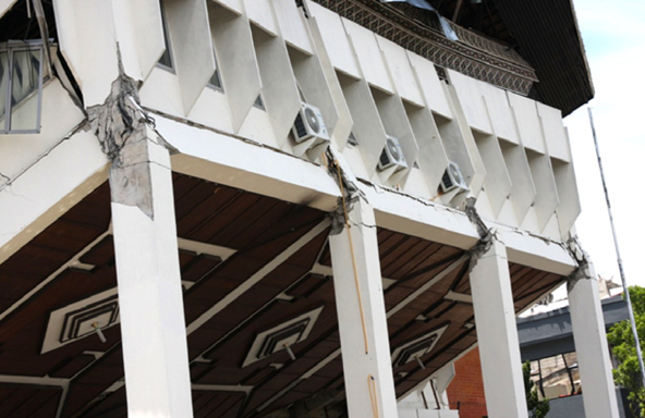
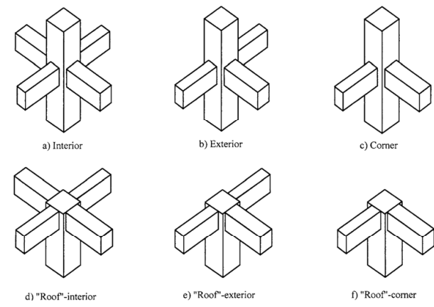
*SEFP Consistent Design**Pile Design**Doc No: 10-00-CD-0007**Date: April 16, 2018* 1.1. FUNCTION OF JOINT Beam-column joint must transfer the forces, such as moment, shear and torsion, transferred by the beam to the column so that the structure can maintain its integrity to carry loads for which it is designed. Another function of the beam-column joint is to help the structure to dissipate seismic forces so that it can behave in a ductile manner. 1.2.WHY DO WE CARE During an extreme seismic event, the code-based structure is expected to maintain its load-carrying capacity for gravity loads even after the structure deforms into inelastic range so that it does not pose any life safety hazard. Hence, the joint can go through significant degradation of strength and stiffness, and if it fails in shear, or anchorage, the life-safety objective of code cannot be achieved. 1.3.CONSEQUENCES OF FAILURE 1.4.THINGS TO CONSIDER FOR BEAM COLUMN JOINT Longitudinal bars of beams, or slab, must be able to develop their yield stress, so that the beam/slab can transfer moment to joint. It means that longitudinal bars must have adequate development length for hooked bars. This implies that the size of the column must be such that bars can develop their tensile forces. If bars can transfer moment, they can also transfer shear as far as monolithic construction is concerned. The shear strength of the joint must enable the transfer of moment and shear through it. The joint should be Constructible: Congestion of reinforcement is the main concern. 1.5.DESIGN SHEAR FOR BEAM COLUMN JOINT The design shear for beam-column joint depends upon the relative strength of beam and column at the joint. For the joints part of the special moment resisting frame, the shear force will be the one that corresponds to the development of hinge in the beam because the frame is required to satisfy strong column-weak beam criteria. If it is a knee joint, then joint area must resist the shear equal to the development of tensile force in the beam. The tensile force will be equal to the product of the area of tension steel, yield strength and the factor that represents the overstrength of steel rebar. If it is not a knee-beam-column joint then, the design shear of the joint will be algebraic sum of tensile force in the beam and the column shear. The column shear is the one that is required to keep the joint in equilibrium, i.e the shear corresponding to the development of the probable moment capacity of beams at the joint. For the joints not part of the special moment resisting frames, one needs to investigate whether the beam or column will yield first. For knee joint, if the column is weaker then the beam, the tensile force cannot exceed the moment corresponding to the development of hinge in column 1.6.THE JOINT: Definition and classification Portion of column within deepest beam that frames in to the column (ACI 352-02). ACI 352-02 categorizes joints based on the displacement-demand imposed by connected members. · TYPE 1 (Section 2.1.1 ACI 352-02) These joints possess limited ductility, and hence the connected members are designed for limited ductility. They are used in situations where ductility of structure is not a concern. · TYPE 2 (Section 2.1.2 ACI 352-02) These joints connect members which designed to have sustained strength under large deformations. Joints are also classified based on their location in framing system 1.7.THE JOINT: Design forces The joint is designed for the shear that results from attainment of the flexural strengths of members connected at the joint for type 2 joints. For type 1 joints, same principle is employed, unless the both members are overdesigned and the engineer does not expect both members, i.e. beam and column, to yield under design forces. 1.7.1. FLEXURAL STREGNTHS: TYPE 2 No strength reduction factor is used for computation of flexural strength. Steel stress is multiplied by factor of 1.25 for computation of flexural strength (3.3.4 ACI 352-02). For type 2 joints, the flexural strength of beams needs to be calculated only, as we do not expect the hinge-formation in columns; we will proportion the beam-column assembly of this joint as per strong-column-weak-beam approach. The slab reinforcement within the flange of beam must also be considered for computation of flexural strength of beam if the slab is integrally cast with beam and if the longitudinal reinforcement of slab is anchored (3.3.2 ACI 352-02). For interior connections, and for exterior and corner connections with transverse beams, the portion of slab to be considered as flange should be as per guidelines of section 6.3.2 of ACI 318-14. The effective flange width should not be taken less than 2 times the width of beam. For exterior and corner connections, without transverse beams, the effective flange width should be as per figures below (section 3.3.2 of ACI 352-02). The effective flange width for this case need not be taken more than 1/12th of the span of the beam. 1.7.2. FLEXURAL STREGNTHS: TYPE 1 For type 1 connection, similar procedure as discussed above should be used, if beams are expected to yield before columns. The stress multiplier factor for this type of connection can be taken as 1. The beam reinforcement, if any, as per section 24.3.4 of 318-14, with-in the effective flange width, must be included in determination of flexural strength in addition to the web reinforcement. If columns are expected to yield before beams, the nominal flexural capacity at beam-column joint should be calculated with due consideration given to the axial load on column. The beam moment in that case would be the one required to maintain equilibrium of the connection. If neither the beam, nor column, is expected to yield at factored loads, then the design shear of joint would be based on factored forces, moments and shear, at beam-column interface.
- 4 replies
-
- 5
-
-
-
- beam-column joint
- sefp consistent design
- (and 1 more)
-
*SEFP Consistent Design* *1997 UBC vertical earthquake term* *Doc No: 10-00-CD-0002* *Date: May 30, 2013* *Article is ripped: Good one to share though* For Strength Design, Ev has the effect of increasing compression and tension/uplift effects on vertical load carrying systems. Ev is not applicable for Allowable Stress Design. The new term, Ev, was introduced in the 1997 UBC. UBC Section 1630.1 defines Ev as the load effect resulting from the vertical component of the earthquake ground motion. For Strength Design, Ev is defined as 0.5CaID. For Allowable Stress Design, Ev is defined as 0. Ca= seismic coefficient from UBC Table 16-Q I = importance factor from UBC Table 16-K D = dead load UBC Section 1630.1.1 defines the earthquake load, E, as the earthquake load on an element of the structure resulting from the combination of the horizontal component Eh and the vertical component Ev. E = Rh*Eh + Ev (UBC 30-1)Rh= redundancy factor defined in UBC Section 1630.1.1Eh = earthquake load resulting from either the base shear, V, or the design lateral force, FpSubstituting the definition of Ev into this equation results in:E =Rh*Eh + 0.5CaID (Modified 30-1)The 1997 UBC defines load combinations in Section 1612. Strength load combinations 12-5 and 12-6include E.1.2D + 1.0E +(f1L + f2S) (UBC 12-5)0.9D (1.0E or 1.3W) (UBC 12-6)Substituting modified equation 30-1 into these equations results in:1.2D + 1.0 Eh + 0.5CaID + (f1L + f2S) (Modified 12-5)(0.9 + 0.5CaI)D + Eh (Modified 12-6a)(0.9 - 0.5CaI)D - Eh (Modified 12-6b) All terms with Eh are effects of horizontal earthquake components. These loads can be in any direction, for example, vertical loads on rigid frame columns, horizontal loads on columns, and diagonal loads on braced frames. Similarly, all terms with D, L, or S are effects of vertical loads or components. These loads can be in any direction, for example, vertical loads on beams, horizontal loads on rigid frame columns, and diagonal loads on braced frames. Example:For typical California values of Ca = 0.40 and I = 1, the modified equations become:1.4D + 1.0Rh*Eh + (f1L + f2S)1.1D + Rh*Eh0.7D + Rh*Eh The impact of the vertical earthquake component on modified Strength Design equations 12-5 and 12-6a is to increase compression effects on columns and foundations. The impact of the vertical earthquake component on modified Strength Design equations 12-6b is to increase tension and uplift effects on columns, anchorage, and foundations. There is no impact of the vertical earthquake component on Allowable Stress Design load combination equations.
- 4 replies
-
- 3
-
-
- seismic load combination
- UBC special seismic
- (and 2 more)
-
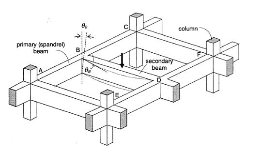
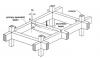
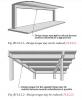
*SEFP Consistent Design* *Torsion: Reinforced Concrete Members * *Doc No: 10-00-CD-0001* *Date: May 24, 2013* Torsional forces, generally speaking, occur in combination with flexural and transverse shear forces. From a design perspective, we need to understand difference between two torsion types: Compatibility Torsion Equilibrium Torsion Compatibility Torsion Compatibility Torsion is when a member twists to maintain deformation compatibility; its induced in structural members by rotations (twists) applied at one or more points along the length of member. The twisting moments induced are directly dependent on the torsional stiffness of the member. These moments are generally statically indeterminate and their analysis necessarily involves (rotational) compatibility conditions(click on the image to enlarge). For the floor beam system shown above, the flexure of the secondary beam BD results in a rotation ǾB at the end B. As the primary (spandrel) beam ABC is monolithically connected with the secondary beam BD at the joint B, deformation compatibility at B implies an angle of twist, equal to ǾB at spandrel beam ABC, and a bending moment will develop at the end B of beam BD. The bending moment will be equal to, and will act in a direction opposite to the twisting moment, in order to satisfy static equilibrium. The magnitude of ǾB and the twisting/ bending moment at B depends on the torsional stiffness of the beam ABC and the flexural stiffness of beam BD. Now here is the fun part, the torsional stiffness of a reinforced concrete member is significantly reduced by torsional cracking. So, if you don’t design your spandrels for compatibility torsion, they will crack, increasing ǾB and reducing the induced twisting moment. To paint the same picture while using ETABS, set your torsional stiffness of the main beam to zero. This will also increase the amount of flexural reinforcement in your secondary beams. Moreover, considering design practice in Pakistan (since we never design beams without shear reinforcement), compatibility torsion can be ignored for regular structures, as minimum shear reinforcement in most cases would stand up to cracking torque. From ACI 318 commentary R11.6.1, Do note that there are some situations (such as circular beams supported on multiple columns) where both equilibrium torsion and compatibility torsion coexist. Also, eccentrically loaded beams, member curved in plan, and member of space frames will be subjected to torsion. See the attached “Timesaving-TorsionDesign-IA.pdf” as a go-by. Timesaving-TorsionDesign-IA.pdf Equilibrium Torsion In simplest words, Torsion is a limit state in this condition; a structure is subjected to equilibrium torsion when it can maintain equilibrium only by resisting the torsion. In such a case, torsional moment cannot be reduced by redistribution of internal forces since the torsional moment is required for the structure to be in equilibrium. From ACI- 318 (click on the image to enlarge). Moreover, see the structures below that defy gravity when subjected to different kind of loads by standing up to equilibrium torsion. Overall Building Torsion For overall building torsion, the torsional effects can be minimized by reducing the distance between the center of mass and center of rigidity. Center of Mass is the point where the mass of an entire story is assumed to be concentrated. The center of mass is crucial as the location of seismic force at a particular level depends upon it. The distance between the Center of Mass and the Center of Rigidity should be minimized, but may not be possible due to building geometry. Invariably, effects of torsion are present in at all buildings although analysis may show that in some buildings torsional effects are negligible.
- 15 replies
-
- 11
-
-
- torsional stiffness of beams
- risa torsion design
- (and 8 more)
-
 *Comments/Observations regarding modelling in ETABS* *Doc No: 10-00-CD-0006* *Date: May 06, 2017* Some of the observations made during extraction of results from ETABS (v 9.7.4), for design of reinforced concrete members, are being share in this article., 1) Minimum Eccentricity ETABS always considers the minimum eccentricity for selecting the design moment of columns irrespective of the probable behavior of the column, whether short or long column. See section 10.10.6.5 and its commentary of ACI 318-08 which deals with minimum eccentricity of long columns. You should always check the design moments that ETABS uses for columns if you want to bring down the cost of construction. 2) Unbraced/ Braced Preference If your model has lateral loads, ETABS will give you design moments in column irrespective of its status as braced or un-braced as per ACI 318 criteria. You should investigate if the storey under consideration is braced, or un-braced (10.10.5.2), and decide appropriate design moments of columns. 3) Time Period ETABS has a tendency to select a time period of the building that is considerably less than the value obtained by the approximate method, Method A, of the section 1630.2.2 of UBC 97. To quote the FEMA 451 document: ''Because this formula is based on lower bound regression analysis of measured building response in California, it will generally result in periods that are lower (hence, more conservative for use in predicting base shear) than those computed from a more rigorous mathematical model". So, there is no need to use the value of time period that is lot less than Ta. One should always check the time period used by the software; ETABS can overestimate the seismic force by more than 2 times. Method A gives lower T and higher V, so FEMA 451 has advised not to use the value of time period less than this value even if rigorous analysis gives a lower value. I have seen the results where Etabs have use the value of time period less than Ta; in-fact as low as 0.5Ta, which can increase the base shear two times. (For a complete discussion on time period, please see the following this thread that complements this section). 4) Stiffness Modifiers First thing is related to modelling the bending stiffness of flexural members, for strength level loads, that is representative of their condition near failure. The ACI code specifies the modifier of 0.35 on gross moment of inertia to represent its condition at yielding. Some people say that the factor should be multiplied by 2 to represent the stiffness of T-beam. This approach would be justified if you are not taking into the account the out of plan bending stiffness of slab. But, ETABS does include the out of plane bending stiffness if you have modelled the slab by using shell elements. So, a factor of 0.7 would overestimate the stiffness of your structure in this case, and will lead to under-design. If one has used the modifier of 0.35 in ETABS for beams in beam-slab floor system, then what value should be adopted for slab? It should not be 0.25, as this value has been specified for flat plates and flat sab floor system. If one is using some value of modifier for out of plane bending stiffness on shells, then the share of the bending moment in beams will be reduced accordingly. This approach is correct if one will be providing the reinforcement in column strips of slab. But, if you are providing reinforcement in slab in the direction perpendicular to supports only, i.e. beams, as is the general practice in Pakistan, then you are under-estimating the flexural demand in beams. Now, there is also a question of factors to be used while deciding the amount of reinforcement required in beams, columns and shear walls. If you are using factors 0.35 for beams and shear walls, and 0.7 for columns, then you are finding out the demand in members at the point of yielding, and this conforms to the code. But, this also means that the structure might experience unacceptable cracks widths. So, if you are using 0.35 for calculating the demand at strength-level forces, then you should also perform crack-control-check at service-level loads by using the factor of 1. If you are calculating the strength-level demand with a modifier of 1 for all structural members, after you have decided the location and the number of shear walls with modifier of 0.35, then you are overestimating seismic forces, as you are underestimating the time-period. But, the structural performance will improve. This article is based on my two separate posts regarding the subject matter. You can view the discussion on the items raised above by viewing the following links: 1) http://www.sepakistan.com/topic/2008-issues-in-etabs-results/ 2) http://www.sepakistan.com/topic/2290-modelling-issuesconsideration-in-etabs/ Thanks.
-
- 6
-
-
-
- stiffness modifiers
- time period etabs
- (and 3 more)
-
Hello Everyone, This log is intended to keep track of all consistent design articles. It would also help me assign the document numbers as the articles come out. If you have an article or post that you will like to get included in SEFP Consistent Design Series, please PM me or any of the moderators. Torsion - Reinforced Concrete Members; Doc No: 10-00-CD-0001 1997 UBC Vertical Earthquake Term; Doc No: 10-00-CD-0002 UBC Seismic Drift Limits; Doc No: 10-00-CD-0003 Diaphragm Flexibility; Doc No: 10-00-CD-0004 (Update Required) Pile Design: Doc No: 10-00-CD-0005 Comments/ Observations regarding modelling in Etabs; Doc No: 10-00-CD-0006 Beam Column Joint; Doc No: 10-00-CD-0007 Bracing Definition; Doc No: 10-00-CD-0008 (Coming soon) Location of Base for Seismic; Doc No: 10-00-CD-0009 (Coming Soon) Long Term Deflection of Beam; Doc No: 10-00-CD-0010 (Coming Soon) Thanks.
-
 Salaam All, Looking forward to develop a series of articles under the title of "SEFP Consistent Design". The aim is to provide simple and lucid examples for our Pakistani Engineers that use UBC 97; examples will serve as quick reference and try to clarify misconceptions prevalent in design offices. Anyone, who would like to volunteer on this is most welcome. As the name indicates, "consistent design" is meant to spread common understanding of complex code clauses that a design engineer faces on a day to day basis. e.g., calculating story stiffness, or designing a flexible diaphragm. Examples would be pure, and written by authors with copyrights to SEFP. Current target is to have at least 2 examples published per month. I hope this will help young engineering to develop a rock-solid understanding and design the right thing rather than saying yes to whatever they are told to follow.That's my goal. Any ideas, input, volunteering in appreciated. Thanks.
- 8 replies
-
- 7
-
-
- Structural engineering forum
- consistent design
- (and 1 more)
-
*SEFP Consistent Design* *Diaphragm Flexibility* *Doc No: 10-00-CD-0004* *Date: August 07, 2014* I am writing this article about a very important, but mostly neglected topic of flexibility of diaphragm. I used to assume that all reinforced concrete slabs can be treated as rigid diaphragms. But as it turns out, only the slab with span-to-depth (depth is length of slab in direction of lateral loads) ratio of less than 3 and without horizontal irregularity can be treated as rigid diaphragm. The more important thing is that the span-to-depth ratio and horizontal irregularity is not the only criteria and one other factor also needs to be kept in mind before assigning rigid diaphragm to concrete slabs in numerical model of building. Another important concept that I learned, and it was a moment of epiphany for me, is about TRANSFER diaphragms. I had posted a topic “Amplification Of Forces In Etabs” earlier in this forum but we were not able to reach at a satisfactory conclusion. Now, I have the answer to that query: Back Stay effect. Another article is required to explain it , and this concept is not discussed in this article. This article is about flexibility of diaphragm. Diaphragms are horizontal members of the lateral-force resisting system of building structures. Their function is to distribute inertial forces, generated at its own level, as well as other levels, to vertical members of lateral-force resisting system. One kind of diaphragm only distributes inertial forces generated at its own level. This kind of behaviour is observed in buildings where there is a continuity of vertical members of lateral-force resisting system: building should not have a setback or podium at lower levels, or below grade levels. The other kind of diaphragm, known as “Transfer diaphragm”, not only distributes inertial forces generated at its own level, but also re-distributes forces coming from upper levels. This type of behaviour is typical of a building having setback or podium at lower levels, or below grade levels. Transfer slabs can attract huge forces due to a behaviour dubbed as BACKSTAY EFFECT. Now, coming to the issue of flexibility of diaphragm. According to ASCE 7-10, In addition to considering aspect ratio and horizontal irregularity as a basis for assuming concrete slab as a rigid diaphragm, the relative stiffness of adjoining vertical lateral load resisting system. Buildings with shear walls at ends and flexible frames in between are the ones where the assumption of rigid diaphragm leads to underestimation of drifts and erroneous distribution of base shear in vertical as well as horizontal direction (1)(2)(3); shear forces in middle frames can be reduced to 23% if rigid diaphragm is assigned in the model (1) for buildings with this type of structural configuration. M. Moeini et al. (2008) (3) conducted a parametric study using numerical analysis and proposed formulae that predicts the error associated with assuming concrete slab as rigid diaphragm. They also concluded that for buildings, without shear walls, rigid diaphragm assumption is suitable for irregular buildings as well. But, for long and narrow buildings with shear walls at ends, the assumption of rigid diaphragm is not suitable. The objective of writing this article was to warn engineers about the tendency of blindly assigning rigid diaphragm to concrete slab in any type of building configuration. The result could be underestimation of forces as well as drifts. Nakashima, M., Huang, T., Lu, L-W. “ Effect of Diaphragm Flexibility on Seismic Response of Building Structures”, In proceedings of 8th world conference on earthquake engineering. San Luis Obispo, MSc Thesis , “ An Investigation of influence of diaphragm flexibility on building design through comparison of forced vibration testing and computational analysis”, 2010. M. Moeini, B. Rafzey, W.P. Howsen, “Investigation into the floor diaphragm flexibility in rectangular reinforced concrete buildings and error formulae”, In proceedings of 14th world conference on earthquake engineering. The article is not finalized and would be completed in coming weeks.
- 4 replies
-
- 9
-
-
- diaphragm
- diaphragm flexibility
- (and 2 more)