All Activity
- Earlier
-

Torsional Irregularity according to UBC97
Zain Saeed replied to Waqas Haider's topic in Seismic Design
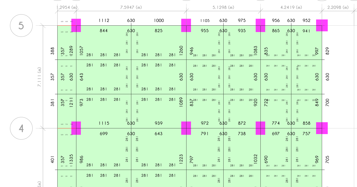
ETABS has various options i.e., Diaphragm Max over Avg Drifts, Story Max over Avg Displacements, Story Max over Avg drifts (Go to display tables> analysis results> joint output> displacement> the options area available here) I noticed some people do this torsional sensitivity check and calculation of torsional amplification factor (Ax and Ay) based on story drift and not on story displacements... the results from each approach gets different ??? also there is another option with Diaphragm so what's the correct approach ??? and how do we know actually what points ETABS has considered for calculation of max/min displacement or drifts.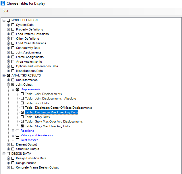
-
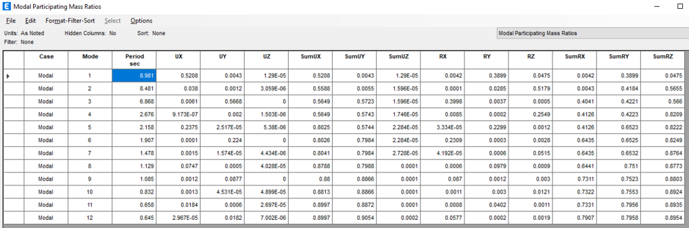
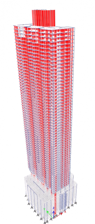
I am working on a high rise building (overall 69 stories, 10 stories of carpark, transfer slab at level 12) located in a very low seismic zone (PGA 5%g). The building first mode is translational (i considered Ux, Uy and Uz tables for this classification) and 2nd mode is torsional followed by 3rd mode again in translational. The modal mass participation ration as shown below. I considered the default 12 modes and getting the required overall 90 percent mass participation both in X and Y direction (Sum Ux and also Sum Uy) but didnt consider the SumUz or ther SUm Rx,Ry and Rz. Is this important ??? I understand that ideally the first 2 modes should be translational followed by torsional mode and this can be achieved with proper structural distribution of elements on the floor plans however for this building the design was freeze and the design team want to proceed. After the response spectrum analysis, i showed them that the higher reinforcement in column and shear walls are resulting from this torsional behavior in 2nd mode. My question is that we have incorporated additional reinforcement tin these shear walls and columns however the slab diaphragm needs any attention ??? or any other element like designing diaphragm particularly at the transfer level to ensure that it receives this torsion and transfer safely to shear walls and columns ??
-
 Zain Saeed reacted to a post in a topic:
Torsion in Buildings
Zain Saeed reacted to a post in a topic:
Torsion in Buildings
-
Zain Saeed reacted to a post in a topic:
Torsion in Buildings
-
do we need to check it for only sum Ux and Sum Uy or others as well ??? Also, how important is to check Rx and Ry while considering an individual mode as translational or rotational ??? Can elaborate this more ..having closer time period for translation and torsional how effects the buidling performance ??? means that the fundamental mode is not the one with highest time period ???
-
Zain Saeed reacted to a post in a topic:
Applying triangular load on plates/shells in ETABS or SAP200
-
Multi-tower building with common podium in Etabs
Zain Saeed replied to Wajahat Latif's topic in Seismic Design
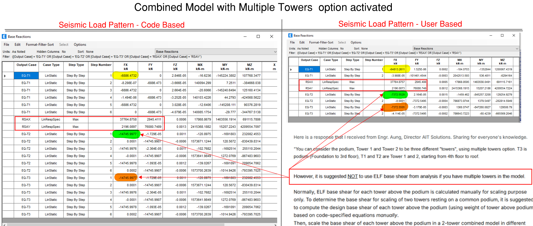
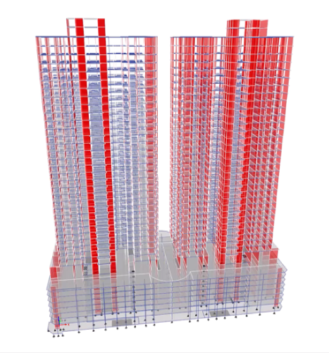
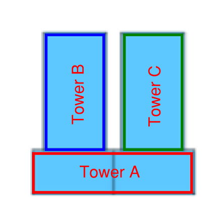
I am working on a multi tower building with a common podium (Fig 1). The initial ETABS model wasn't built using multiple tower option however during the seismic design incorporation, i activated this "Multiple tower" option in ETABS and accordingly set podium to T1 and T2 and T3 for the remaining two towers (Fig 2). Afterwards i partially exported the towers and performed the analysis to get story forces from individual tower models. These forces were finally added as user defined seismic load in the full complete model (Fig3) As mentioned above that not to use ELF base shear, i initially thought it shouldn't be an issue. However later after analyzing the complete full model with multiple towers i realized, that it almost showed double base shear from ELF in case we go for automatic seismic load (based on code) compared to manually applying the story forces on the towers (Fig 4). I am not sure if its some modelling mistake and trying to figure out why there is much different in static load case however the response spectrum from both models show minor difference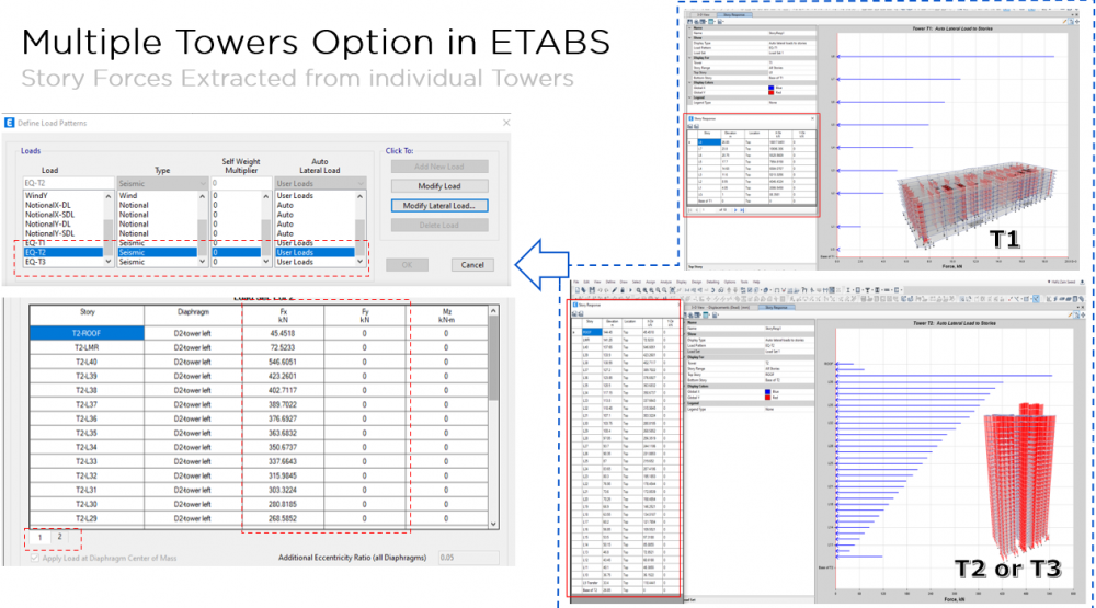

-
Zain Saeed reacted to a post in a topic:
Multi-tower building with common podium in Etabs
-
Yes, as the approximate period is simplified and often conservative compared to more accurate one obtained from modal analysis which reflects actual stiffness, mass distribution, and geometry of structure
-
Multi-tower building with common podium in Etabs
Zain Saeed replied to Wajahat Latif's topic in Seismic Design
@Wajahat Latif Can you further elaborate on the above point -
Multi-tower building with common podium in Etabs
Zain Saeed replied to Wajahat Latif's topic in Seismic Design
Can share and elaborate the different load combos required for the towers which are resting on a common podium and how these are different in case a seismic joint is there ?? Also what design consideration have to be taken for the diaphragm at top of podium where the towers are resting ??As i believe that out of phase movement for the 2 towers will generate high internal forces at the podium diaphragm. Does ETABS automatically considers them or we need to manually define some combinations for such scenarios ??? -
Zain Saeed reacted to a post in a topic:
Multi-tower building with common podium in Etabs
-
what is our ultimate goal by making reduction in members stiffnesses in softwares ?? i know the concept but i do not know the sense behind this in terms of the practical advantages will get after doing this and what will happen if we did not .
-
hi engineers , May i know why we have to rely on meshing to govern our programe results and hence the design , if result is going to be affected by meshing how colud we get the accurate result for safe design ??? and to what limit can we depend on meshing ?
-

SOFTWARE NEEDED FOR BAR BENDING SCHEDULE
G_Farooq replied to Tstruct's topic in Spreadsheets & Softwares
Just use excel. Make a simple worksheet listing bar dia, number, length for each element. Bar weight tables are available online. OR If its a building and you have the Etabs model. Run the detailer, it will give weight of steel required for each floor or member wise. Staad Pro also gives total steel weight and concrete volume for the model -

SOFTWARE NEEDED FOR BAR BENDING SCHEDULE
UmarMakhzumi replied to Tstruct's topic in Spreadsheets & Softwares
W/Salaam, Do you know Python? You can use ChatGPT or any other AI platform to write code for python or any other language. It can probably create a visual basic script for you as well that you can use in excel. Thanks. -
Assalam u Alaikum, I need a software for bar bending schedule and ultimately calculating the weight of steel. I am a structural engineer and this quantity calculation is not my field but I need it for some specific task. Can someone guide me which software free or pirated is available out there?
-
Can design time period be different than approximate time period? Also what conditions ensure no time limit for seismic drift calculation?
-
Hi friends Please I need detailed calculation about how we can considered accidental torsion for response spectrum. If there is any hand calculation example it will be better. Thanks in advanced
-

Connection Of Truss To Supporting Beam Column
Hafsa Azmat replied to Hasan Tariq's topic in Steel Design
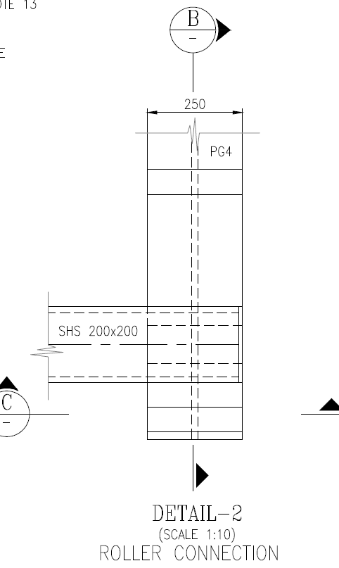
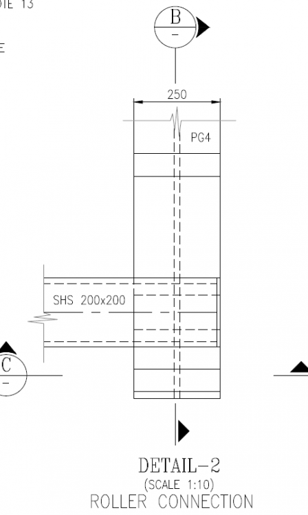
Hi, I have a similar scenario where the truss is subjected to both wind and temperature loading. I have assigned a hinge and roller support to the truss; the roller is translating in both directions because of wind and temp loading. To accommodate movement, I am using a ball bearing with stopper plates to restrict excessive displacement while providing the necessary deflection allowance. My Questions: 1. If the ball bearing comes into contact with the stopper plate at its extreme deflection limit, will the connection start behaving like a hinge? If so, do I need to check my truss supporting beam for additional reactions due to hinge behavior? 2. Would using a Teflon bearing plate solve this issue, or would it also behave like a hinge once it reaches its displacement limit? ( I donot know teflon plate behaviour) For example, if the truss deflection exceeds the allowable displacement range of the Teflon plate, will it introduce unintended forces at the connection? just like roller and stopper plate connection Would appreciate insight, Thank you Please advice

-
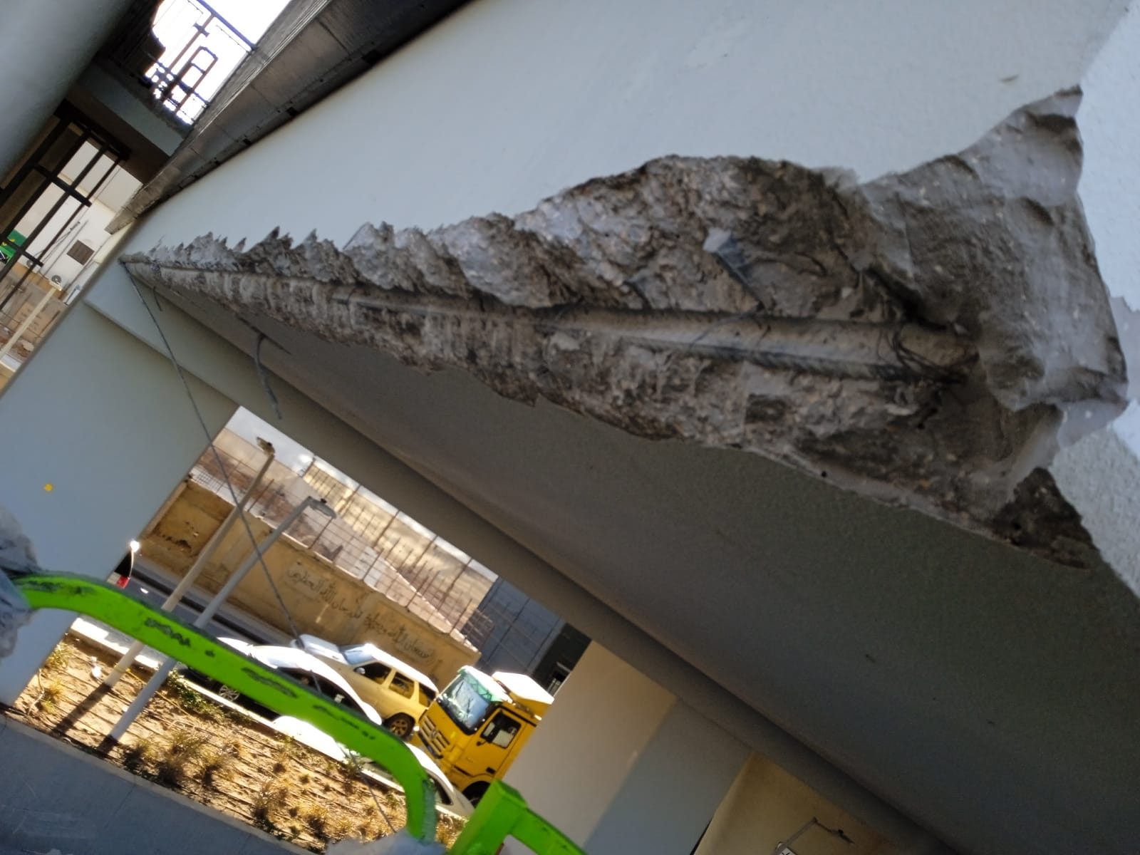
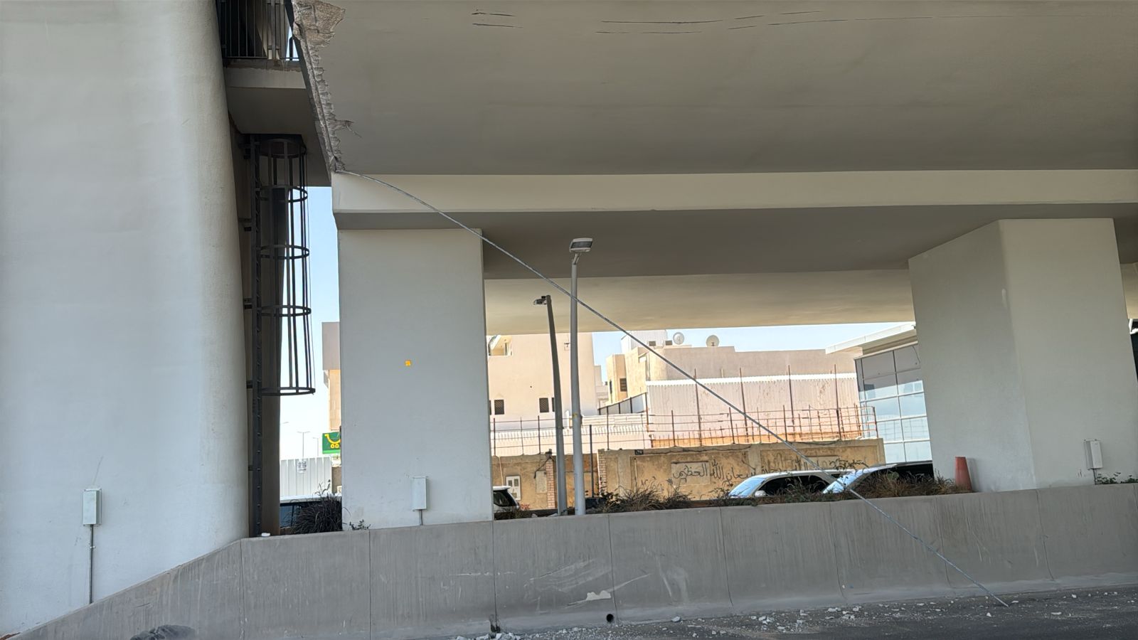
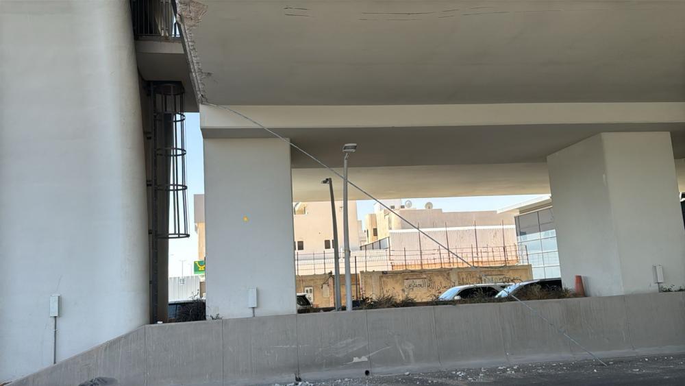
 Hi, Greetings sagacious colleagues, As per the attached pictures, could anybody assist me regarding the following concerns, Why is NDT required, if not why? Method of repair and what will be the plan on the damaged reinforcement, especially the main bar, will it be cut and use a new one through spliced (welding, stirrups, etc.)? Which type of material is to be required? Thank you.
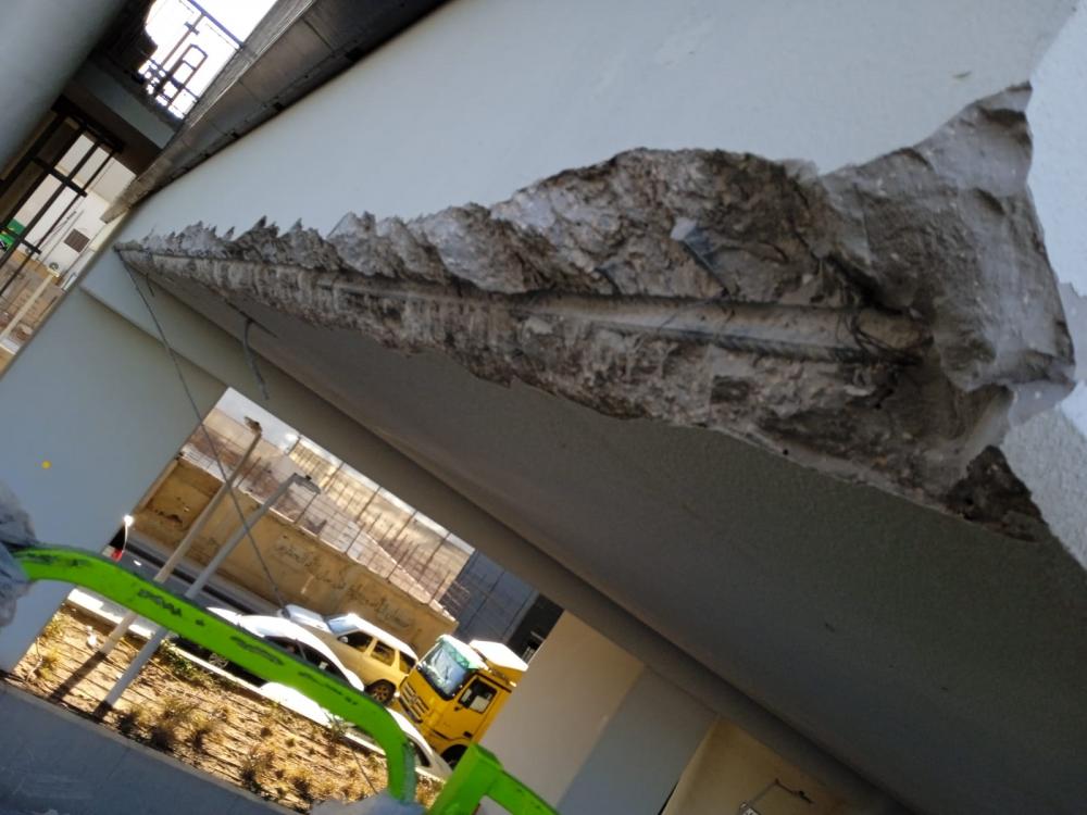
-
Strength design lateral loads
-
Should drift be checked in strength design condition or service condition of structure?
-

how to consider bouandary columns in shear wall
Tiger Hổ replied to BENTAFAT's topic in General Discussion
etabs solve this quite good. or you can use prokon to calculate shearW -
Cantilever beam failure no matter the size
Tiger Hổ replied to Alisha Pradhan's topic in General Discussion
Send the model included. 3m is too long for a normal cantiliver beam -
 Joint assignment for RCC Wall in basement in a frame structure modelled in SAP2000 Hello, I am designing a frame structure in SAP2000 which has a RCC wall in basement upto the bottom of floor beams. Should I divide the wall into 2'x2' squares and then assign fixed supports to all the wall shells or not?
 -
The cantilever beams fails in shear even if the size is increased. Can torsional modifier of 0.001 be applied on these beams considering the case of compatibility torsion? or is this the case of equilibrium torsion?
-
Dear Members, I am currently designing a warehouse with a span of 125'-0". The structure is being modeled as a metal building. Deflection is within allowable limits, but 6" deflection could disrupt roof components. Reducing the deflection further makes the metal building design uneconomical. To address this, I'm planning to design truss frame for comparison. Could you please recommend a suitable type of truss to resolve these issues? Additionally, any special guidelines for truss design would be greatly appreciated. Thank you in advance for your assistance.
-

Difference in result betwen FEM and strip in SAFE
FouziBel replied to Leomessi90's topic in Software Issues
Hi there, I had the same issue, and the FEM results in tables are per unit width (1 m), so Modeled the strips with 1 m width, and the results are way much different (almost 50% less than those on fem results table !! so what would be the problem? -
Did u find the proper way . what should be the modifiers for wall resisting soil load in one side of building. since its part of building what should be modifier used