Leaderboard
Popular Content
Showing content with the highest reputation on 03/03/13 in all areas
-

Artisan Trainer Guide!!
UmarMakhzumi and one other reacted to Waqar Saleem for a topic
Dear members i came across some nice documents which are very helping for the engineers working on sites so that they can train their masons and artisans and improve the construction practices also construction industry will have good labour force which ultimately will ultimately improve the structures. M2_S2_RCC frame structure.pdf M3_S1_Repair and retroffit.pdf M2_S4_Quality control.pdf2 points -

Difference In Etabs And Sap2000 Results
Waqar Saleem and one other reacted to UmarMakhzumi for a topic
I did a quick manual check. Moment is 195 k-ft consider the 2k load at midspan is a dead load. There is something wrong with the 274kft model input. You can make another model for comparison and just apply UDL loading only to see comparison or point load only to see comparison. Both results should be same as what you manually calculate. Have a look at your reactions.2 points -
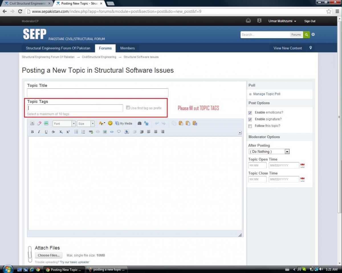
Using "topic Tags" When Posting New Topic
Ayesha reacted to UmarMakhzumi for a topic
Salaam Everyone, I would request you all to fill out the Topic Tags box when posting a new topic. See the attached file. It helps list similar thread so that a person can easily locate information on the forum. It is very important. Please uphold the request and use tags as much as you can. Just type things related to your topic and press comma to separate tags. Thanks 1 point
 -

Post Tensioning Slab
Ayesha reacted to Sajid Usmani for a topic
Not beams exactly but Band-Beams can post tensioned easily and economically. It is common especially for large spans. Pl see the book Bangali S Taranath. It is not necessary every time PT slab is economical or feasable. Soon you will see it is hapenning in Karachi. It has been designed but unfortunately not executed yet. Hope this time it happen.1 point -

Using "topic Tags" When Posting New Topic
UmarMakhzumi reacted to WR1 for a topic
Yeah i was thinking abt it too...i will start putting tags for previous posts too...its the best way to appear in search1 point -
Difference In Etabs And Sap2000 Results
Waqar Saleem reacted to WR1 for a topic
just look at the pictures posted by you, its evident that in ETABS you did not specify the end offsets. In ETABS (look at the moment diagram) moments are reported at the face of support. In your example moment of beam is reported at the face of column, while in sap to the centerline of column. If you want to compare then in ETABS select the lines and make their offsets = 0 Please upload the models too, so I can check it.1 point -
Issue With My Results In Etabs Model
Ayesha reacted to UmarMakhzumi for a topic
that is a different perspective but "Outrigger action"; is in-plane too & is building mai to koi significance nahin ho ge. Anyhow, I will go through it on weekend to see what potential effects it has!1 point -
OUT OF PLANE stiffness reduction results in more sway because in dynamic analysis we assume that we have rigid diaphragm supported by flexible columns this rigid diaphragm is rigid "in-plane" thats why at any point we will get same sway what i was talking about was not for MEMBRANE (where out of plane stiffness is zero) i was talking about SHELL element which has significant out of plane stiffness....and this out of plane bending causes outrigger action or frame action which causes changes in stiffness and hence the lateral sway if you include shell in your model it will stiffen the building due to this effect now if you decrease the shell stiffness (out of plane) ofcouse its lateral sway will increase... on the other hand if you are talking about membrane only (classical) dynamic approach we dont take this effect...1 point
-
Issue With My Results In Etabs Model
khalid reacted to UmarMakhzumi for a topic
For stiffness modifiers to slabs, If your framing is such that you don't have Stiff Beams (beams normally > 3*Depth of slab), you will see a lot of difference when you apply and don't apply stiffness modifiers. Consider flat plates, where you have thick slabs on periphery beam. Now when you don't apply stiffness modifiers to such a case, you get less moment in you beam as more load is transferred by the slab to the column, and slab is considerably thick and has a reasonable stiffness relative to the beam which is supporting it. For the same case when you apply a modifier, the slab stiffness is reduced and more load in transferred to your beams which are now stiffer than your slab because of the modifier. Why should we use a stiffness modifier? for the above example, a flat plate would have some sort of cracking when subject to seismic loading and because of that the stiffness would be reduced, as a result the beams would be carrying higher load than they were actually supposed to take(considering if the original design was based on no stiffness modification for slab). Thus by using modifiers for this case, a structural engineer is able to consider the effect of heavy loaded beams and designs beams to a greater load. Therefore, using stiffness modifiers where there is a reason can help you design robust structures. What I am trying to say is that for slabs like 4", 5" the difference in moments is very small for the cases with or without modifiers if the beams are deep. Don't worry too much about using modifiers unless you have a condition that demands one. Just, plug your numbers in and do your analysis as for most of the general cases, the difference due to modifiers would be close to nothing as explained above. Every thread I go, people are confused about them. Dont worry that much, just use the default numbers and be cautious of situations like the one explained above where you really need them. @Rana, why did you say that using stiffness modifiers for slab would result in higher sway? Isnt the lateral distribution (for this case) on rigid diaphragm assumption would result into same story force no matter how thick or thin the slab is, which will determine the story sway(considering frame stiffness as constant)..1 point -
Tallest Building In Pakistan
haro0n reacted to UmarMakhzumi for a topic
This building promises to be tallest in Pakistan when completed. Project Description: Bahria Town Icon consists of two towers which are identical up to 8 floors i.e. 7 basements for car parking and 1 ground floor. Tower-1 comprises of 70 levels for office space and Tower-2 comprises of 30 floors for residential purpose. Client: AAA Partnership (Pvt.) Ltd. - Karachi. Location: Karachi. Architect: Arshad Shahid Abdullah (Pvt.) Ltd. - Karachi. Engineer: ESS-I-AAR - Karachi. (Structural) Beg Associates - Karachi. (Structural) WSP - UAE. (Structural) CFA: 2,230,500 m2; (24,000,000 ft2) Estimated Cost: USD 162.5 Million (PKR 13 Billion) START DATE April, 2010.1 point