Leaderboard
Popular Content
Showing content with the highest reputation on 07/25/15 in all areas
-

Design For Shear And Torsion Using Etabs
Beenay Shahi reacted to Hasnain Khan for a topic
Hello, I have recently joined a structural engineer, and trying to get myself familiar with the norms of practice, so I have some basic questions which I haven't been able to get answers of sufficiently. After modelling the structure in ETABS I'm trying to find out how to interpret the values of shear and torsion reinforcement given in design outputs. I have tried to find the answers by codes, manuals but haven't succeeded. Even asking my colleagues haven't given a satisfying answer, as everyone has his/her own way of interpreting these values. Thanks,1 point -
.thumb.jpg.700916fbc7ead330085e15745d0270bd.jpg)
Shear Reinforcement In Etabs
Beenay Shahi reacted to Waqas Haider for a topic
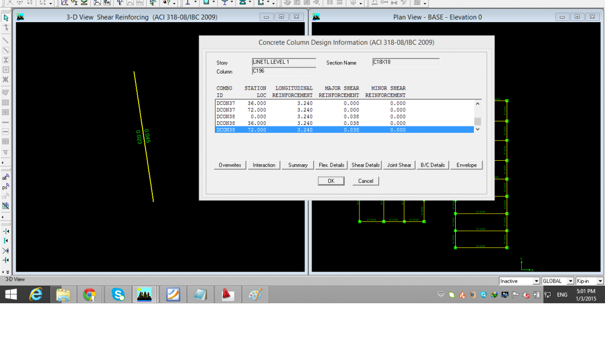
Assalam o alaikum. I have just designed a frame structure with SMRF. The out put of shear seams weird to me. Column reports design shear Av/s as 0.045. (Images are attached). but when i right click the member, it must show me the most critical case HIGHLIGHTED AUTOMATICALLY. But it highlights load combo 38 (auto-generated combos have been used) which reports Av/s as 0.038. And 0.045 value is at combo 32. Is their any logic behind it?? More over how to interpret this Av/s?? means 0.045 in kip-in units means what? How can i convert this into spacing?? 1 point
 -

Opening Near Columns
Beenay Shahi reacted to mhdhamood for a topic
Dear All; I have a problem in design for punchings for the attached case.Since the column near an opening : 1. Do I need always to deduct the ineffective length as I draw in fig.1, whatever the length of the opening??? 2. why not consider the opening like a free edge then the effective punching perimeter will be good and taller ??? 3. If I need to provide a drop panel and I have 8 meters spans that means it will be 8/3 meter its dimenstions or I can provide lesser dimensions like 1meter ??since I need it to resis punching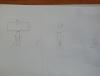 1 point
 -

Shear Reinforcement In Etabs
Omer Ahmed reacted to EngrUzair for a topic
Assalam-o-alaikum! Shear reinforcement values indicated on the column member are generally the maximum values for the two shear axes, whether these are from on load combo or from two different load combos. Right-cIick on the member reinforcement diagram generally leads straight to load combo resulting in the maximum longitudinal or maximum shear reinforcement. However, as you have indicated, I am unsure, why this does not always happen. Surely, someone else might be able to explain this. Interpretation of shear reinforcement value 'Av/s', given by ETABS, is not very difficult. Since your units are 'kip-in", Av (i.e. cross-sectional area of ties) is in 'sq.in.' and s (i.e., spacing) in 'inches'. For your case, Av/s = 0.045. For 2-legged #3 ties, Av = 0.11x 2 = 0.22 sq. in. Substitution of value of Av in above equation, results in required tie spacing, s = 0.22 / 0.045 = 4.88 in. Regards.1 point

This leaderboard is set to Edmonton/GMT-06:00