Leaderboard


Popular Content
Showing content with the highest reputation on 05/17/17 in all areas
-

Centre to Centre Modeling
Kainaat reacted to Saad Pervez for a topic
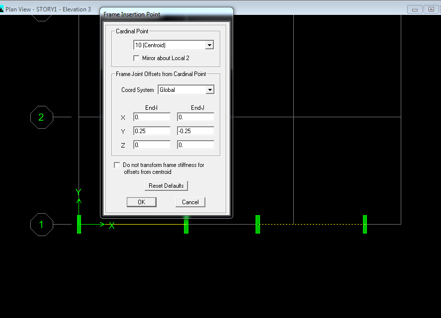
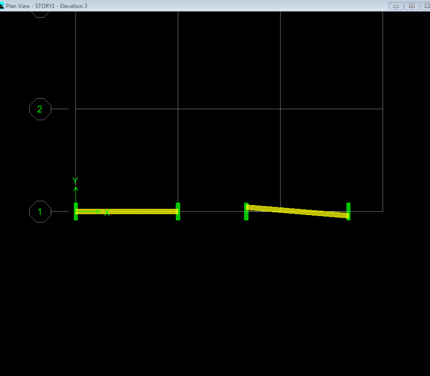
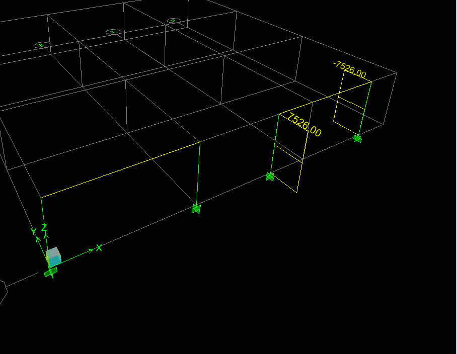
You should do center to center modelling for this structure and to capture the eccentricity, you can either model the column as shell element like Sir Rana said or you can use insertion points for beams, always look at the extruded view to know the actual arrangement of the elements you're modelling. I'll illustrate the use of insertion points, you can use the approach you find suitable. Insertion points will capture real world behavior by keeping your Finite Element model closer to reality. Consider the 2 beams below, the are exactly the same, they look exactly the same. We'll select the beam on the right hand side and go to assign>frame>insertion points. And "insert" the beam with eccentricity of 250 mm at both ends. End-I with a positive eccentricity and End-J with a negative eccentricity, (don't forget to uncheck the box!) Then we look at the extruded shape again, we notice that the beam is inclined now (which matches your case). If we look at the "unextruded" view, both beams will look the same. We run the model, we can see that the values for shear force are different because ETABS is calculating forces based on inclined length. If eccentricity is captured, there should be a moment in 2-2 direction. Which we can see is there and is numerically equal to P*e = 30103.99*0.25 = 7526 kN-m Hope this helps.

 1 point
 -
Also see Modern structural analysis book by Iain A Macleod section 5.6.5 Eccentricity of members at a joint, if you want to go deeper.1 point
-
I could not find a clear reference for this. This brings us to another topic of uncertainty (As structural engineers, we deal it every day). Of course, this problem in the post could be more rationally solved by sound engineering judgement, but I want to highlight the approximate methods. When there is uncertainty, try to be consistent all the time. Errors and approximations are obvious in structural analysis. Just keep consistency. For example, personally I'd like to keep the Y/X in these cases, less than 10% (strictly speaking 8% based on 500 Y and 6000mm X). Set a criteria for yourself and follow the same approach in modelling assumptions. What are these X and Y, well Y is the center to center distance of columns, and X is the distance between these columns (or the span of beam). What I could discern from the provided image is that; Y=1.8' X=5.3+7.5=12.8' so the beam connecting center to center has an in-plane slope of 14%. a. Of course the first approach in the pictures provided is not accurate as other members have pointed out. b. Second approach is also not suitable as the slope is more than 8%. However, This could still be done if column sizes are more than adequate as compared to spans and loading. In your cases the bigger column size is almost 28 inches, so in my opinion should not have much problem due to this eccentricity. But.....visually the situation looks awkward, although ETABS is not Sketchup, but things like that will draw attention of the reviewer/checker of your models and probably will focus more in this area. In order to avoid this use option c below. 3. Model the bigger column as a shell element with just one support point (important) at the base.1 point

This leaderboard is set to Edmonton/GMT-06:00