Leaderboard
Popular Content
Showing content with the highest reputation on 09/16/17 in all areas
-

Load Patterns,Combination,Cases
Engr. Muhammad Usman Khan reacted to EngrUzair for a topic
See the following links for clarification: 1. Load pattern 2. Load case 3. Load combination Regards.1 point -
R value for Minaret structure..
Ali Sufyan reacted to EngrUzair for a topic
IMO, if the lift core consists of RC walls and columns are part of a frame system, it may possibly be considered a Dual System consisting of RC shear walls with IMRF (R=6.5) or simply IMRF ( R=5.5). Otherwise, the minaret might be considered to correspond to "Distributed mass cantilever structures such as stacks, chimneys, silos and skirt-supported vertical vessels" (S/No. 3 in UBC-97 Table 16-P), for which R=2.9. HTH Regards.1 point -
.thumb.jpg.700916fbc7ead330085e15745d0270bd.jpg)
Shear wall design
Jairo González reacted to Waqas Haider for a topic
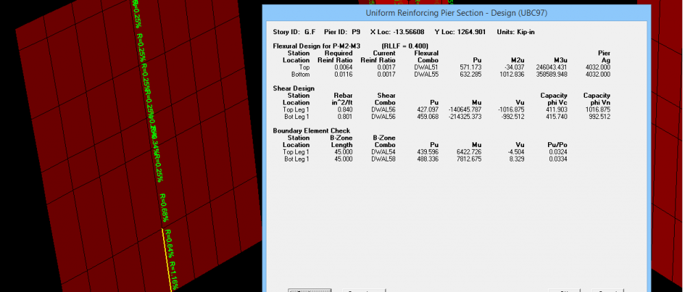
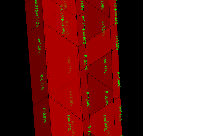
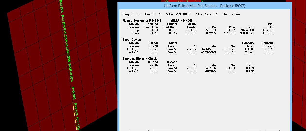
Last month, i design a structure with shear walls. I will attach more documents. What i know/remember i will share with you. In simple, Pier is similar to column and Spandrel is similar to beam. Shear wall is modeled in etabs as shell element. You are to assign it either pier label or spandrel label (Depending on situation of shear wall) to design a shear wall. If you want to design a shear wall, it mostly needs peir label to be assigned. But for the portions of shear wall above openings, as its behavior is somewhat like beam resting on two supports, you need to assign it a spandrel label. I have attached screen shots of my model where you can see i have assigned pier label to the vertical elements and i have assigned spandrel labels to the elements spaning horizontally above openings. The reason behind is detailing based. The detailing in vertical elements of shear wall is similar to wall (or column) and its design is based on considering it as an element resisting majorly AXIAL FORCES + MOMENTS along with inplane shear forces. (Theoratically it acts as a cantilever beam spaning vertically which again represent behavoiur similar to column). I have also attached screen shot of design detail of pier which reports total vertical steel in wall with respect to section area for resisting moments, horizontal steel for resisting shear and some times boundry elemtns (i.e. special detailing at ends of shear wall exactly as in column i.e. shear rings confining vertical bars). I have also attached screen shot of design detail of spanderal which reports top steel, bottom steel, to resist moments similar to beam and vertical steel to resist shear along with DIAGONAL reinforcement some times needed to account for reversal of forces. I will attach more documents throwing detailed light on shear wall design i found few weeks ago. Also my model is attached (it is in seismic zone 4 from where you can get idea about pier labeling and spanderal labeling) One important thing is that, pier label and spanderal label also meant to integrate forces. i.e. if you assign same pier label to all walls in a floor connected with each other, the software will report results only for one and critical wall because all walls were assigned only one pier label. If you want to have multiple outputs at multiple walls, you should assign them different pier label. in image number 5, note that i have not assigned any pier to the selected portion of wall. hence no reporting of results is done. Etabs Center Portion.e2k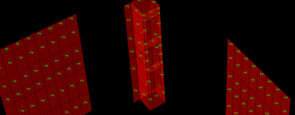

 1 point
 -

Shear wall design
Jairo González reacted to WR1 for a topic
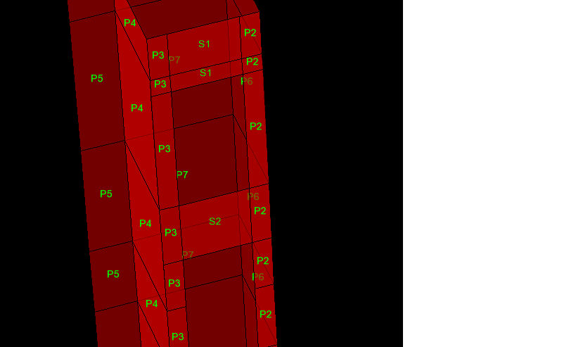
This is absolutely wrong practice. 1. PIERS Assign as per option a (See image posted by sir Makhzumi in previous reply) Why didn't you apply pier to spandrels. Most people do not apply piers labels to spandrels. Give up on that. Lets talk about this image. The top floor. Piers go horizontal with same number. 2 shells of P3, 2 shells of P2 and 2 shells of S1 should all have been defined as one pier. Then P2 and P3 slender piers below them should be assigned different pier names separately. Infact, as flexural deformations are dominant in these slender piers, divide them (mesh) into 4 pieces and assigned different pier to top 2 shells and different to bottom 2 shells (depends on the moment diagram though). 2. SPANDRELS Assign as per option a (See image posted by sir Makhzumi in previous reply) The spandrel I see in image is a deep beam. Isn't it? L/D < 4? If so, where is the meshing? If its not a deep beam then apply different spandrel labels to each shell atleast in the middle for postive moment design.0 points

This leaderboard is set to Edmonton/GMT-06:00