Leaderboard
Popular Content
Showing content with the highest reputation on 03/02/19 in all areas
-

Design base of steel column subject to axial load and biaxial bending
UmarMakhzumi reacted to Abdallah Hassan for a topic
Thank you for reply the solved examples in design guide is only for design base subject to uniaxial moment and axial force only, and I am looking for design base subject to N,Mx,My1 point -

Slenderness of Columns
abbaskhan2294 reacted to EngrJunaid for a topic
The quick method to check weather the design of slender column is fine or need to increase the column size are as follows; 1- In order to get the moments along column height accurately, divide the column into 2 or 3 segments. 2- Apply modifier. 3- Activate the P-Delta option from define menu. 4- Run the analysis and design with P-Delta and check the Non sway magnification factor i.e. delta(ns) in design summary of the column (see the pic attached). This delta(ns) must be less than 1.4. If this exceeds the limit of 1.4, increase the column size otherwise the column design is OK. Correction by seniors in my above steps will be highly appreciated.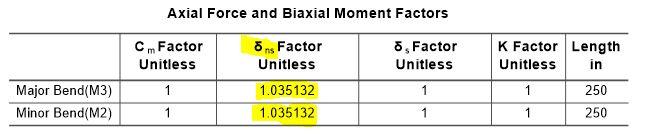 1 point
 -

Simply Supported Beam Model As Shell Element
Hafsa Azmat reacted to UmarMakhzumi for a topic
Saiful Islam, I like your curiosity and your question is good too. Generally for beams, if you wan to do 3-D modelling, solid elements should be used.The definition below would help you understand the difference: To simplify, shells elements are best for walls, slabs and modelling 3D elements where the thickness is smaller like surface elements. Hope this helps. Thanks.1 point -
Structure stability calculations
hali reacted to UmarMakhzumi for a topic
Hi Anton, You need to create a free body diagram and do strength and deflection checks . For that, you will need some information from the architect like building plans to estimate mass per floor and structural framing drawings to idealize your structural for hand calcs. Thanks.1 point -

Shear Reinforcement In Etabs
Omer Ahmed reacted to EngrUzair for a topic
1. In the following explanation, I am referring to ETABS version 9.7.4, with active units of 'kip-in' for all quantities. You are probably using ETABS 13 or later version. In these later ETABS versions, systems of adoptable units have been improved, and new options of units have also been implemented. However, in order to understand the explanation given in the following, you will need to change active system of units your model to 'kip-in' for all quantities. Otherwise you might miss some important point. 2. In case of beams supported at both ends, shear force (& accordingly, shear reinforcement) is more near the beam ends, as compared to middle portion of the beam. For these beams, ETABS indicates shear reinforcement at 3 points along the beam _ at the start, at the middle and at the other end of beam span. If the beam is not subdivided into smaller parts, shear reinforcement value would generally be larger at both ends, as compared to that for the middle portion of the beam.(Beam in your attached image is indicating the similar results.) 3. Calculation of required stirrup spacing is similar, to that described for the ties in case of columns in my earlier post. 4. Upto which distance, what stirrup spacing is to be provided depends upon the shear force distribution along the beam, as will be clear from shear force diagram for the controlling load combination. This spacing will however subject to relevant provisions of ACI 318-08 Chapter 21, depending upon the earthquake zone or design category of the area in which your structure is located. 5. Now referring to the beam shown in your attached image, the value shown in the middle (0.1000), indicates maximum required shear reinforcement applicable to middle portion of the beam, whereas the other two values (0.1521 & 0.1351) are the maximum required shear reinforcement, to be placed at the relevant beam portions adjacent to supports (columns) on the relevant ends. In case your lengths in 'inches', and shear reinforcement in in 'sq.in/in.' units, you may calculate required stirrup spacing, similar to column tie spacing discussed earlier, keeping in view relevant ACI requirements. 6. For exact detailing of the 18 ft span referred beam, following further information is required: a. Overall Beam size (width & height) b. Image showing required shear reinforcement values, after changing the active units to 'kip-in' for all the structural parameters, similar to ETABS 9. It would be better & simplify the detailing a lot, if the beam is subdivided into 4-equal parts, before analysis. c. Earthquake zone or seismic design category of the area in which the structure is located. c. Structural frame system used (OMRF, IMRF, SMRF, etc.) d. Minimum reinforcing bar size used for flexural reinforcement of this beam e. Preferable bar size for stirrups (Normally #3, or #4 bars are used). Regards.1 point