Leaderboard
Popular Content
Showing content with the highest reputation on 07/10/20 in all areas
-

Guidance with regard to the detailing of beam in seismic zone
Osama Anwar reacted to Simple Structures for a topic
1. Apologies - I can only think in metric units - so ASSUMING all the above numbers to be metric units , for argument sake, Then, If L/4 = 2.75, then L = 11 m Therefore, 0.15L = 1.65m + depth of beam ..... which you say then totals 3.835m : This would mean your beam is 2.185m deep (L/5) which cannot be right! Get an Engineer in your office to check you numbers! With regards to rebar from fixed ends: Left or right , one would take 100% of the reinforcement for distance GREATER THAN 0.15L+h, then take 60% to distance 0.3L+4, and so on. You could decide to take 100% to 0.3L+h length. It depends how many bars you have in top. These are detailing rules are guidance and you as the engineer need to make safe choices based on that. For example, If you have 2 bars on top as 100% reinforcement, at say 0.15L+h you can splice them with smaller bars (60%), than after 0.3L+h, you can splice them again with small bars to take 40% etc. With so many splices, this is not practical, increases tonnage of rebar ... so based on ones engineering judgement, one would take the two bars to say 0.3L+ha and splice there with two small bars and just have two bars in top..... remember you have to do this from both ends, so it may be better and practical to take the 100% bars all the way across the top of the beam. If you had 5 bars on top, you can go continue with say 3 bars after the point beyond 0.15L+h (stop two there) and then you are continuing on with 60% etc. With seismic loading you will get M reversal at bottom (-ve M) so you may need to follow same rules for bottom bars. ------------------------------------------------------------------------- 2. Secondly, you must appreciate anchorage of top (& bottom) bars into the column needs to be sufficient to avoid joint failure. Calculate the anchorage length as shown "blue" on sketch below.... what the computer printout illustrates is inadequate! Your joint will fail under seismic loading .... or use long U-bars at ends in the beam. You must provide sufficient anchorage of beam bars into the column, both top and bottom bars.... Calculate anchorage length from centre-line of the column ! Master "reinforcement curtailment into the beam &, anchorage into the column or wall". 3. The BM envelope will come from gravity loads + seismic loads. Most computer programme give the BM diagrams envelopes for various load combinations. Like I say I am not a ETABs user, leave to that to others to advise. Below is an example - based on Eurocode EC2, the code i use - for beam pinned at LH side and continuous on the right... showing typical reinforcement curtailment based on BM. This is a general illustration only, and shows how BM Envelopes and Curtailment of reinforcement works. When I trained as a structural engineer I had to follow a training sequence and learn three things: 1. Work as reinforcement detailer/draughtsman for two years, then work out and draw bending moment diagrams by hand for another few years for beams and frames, and then design by computer!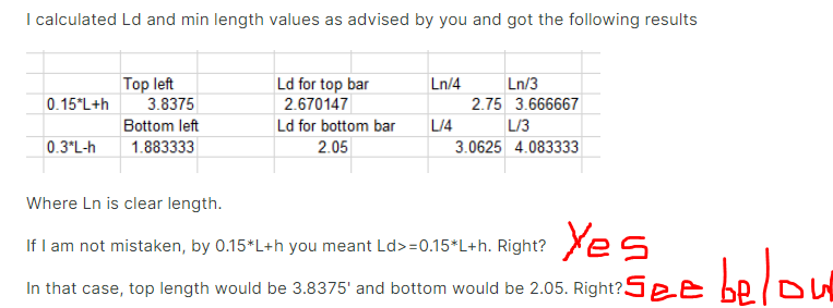

 1 point
 -

Insertion Points and End Length Offsets in ETABs
UmarMakhzumi reacted to Badar (BAZ) for a topic
Yes, if you are using insertion points, do not use rigid links. I am more comfortable at using rigid links. Having said that, it will not make notable difference in most situations. Unless the eccentricity is more than 9 inches and there are long spans (more than 30ft).1 point -
Guidance with regard to the detailing of beam in seismic zone
Osama Anwar reacted to Badar (BAZ) for a topic
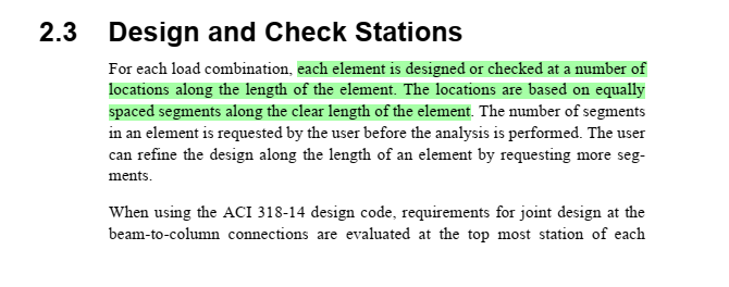
ETABS divides the region of member to report forces and perform design based on the option shown in attached screen shot. You can divide the member into different regions either by specifying minimum number of stations(sections) or maximum spacing of stations(sections). The default setting is that it will check the beam at every section located at 500 mm distance along the clear length of the member (max station spacing). See the attached screen shot of the ETABS's manual (CFD ACI 318-14) as well..thumb.png.b4275cf25f0183d721cf3bb17f371ae4.png)
.thumb.png.33a8db478347162036146b7cde6c200d.png)
 1 point
 -

Reinforcement Overrides for Ductile Beams
Shahzad Khan reacted to UmarMakhzumi for a topic
The posted video above by Ayesha answers the question. Thanks.1 point -
Structural Engineering Books
shazeb mirza reacted to Badar (BAZ) for a topic
Reinforced concrete structures, R. Park & T. Paulay Design of Reinforced Concrete, Jack C. McCormac & James K. Nelson Reinforced Concrete, Edward G. Nawy Prestressed Concrete, Edward G. Nawy Design of Prestressed Concrete, Arthur H. Nilson Prestressed Concrete Analysis and Design, Antoine E. Naaman Finite Element Procedures, Klaus-Jurgen Bathe The Finite Element for Solid and Structural Mechanics, Zienkeiwicz & R.L. Taylor Structural Analysis, Aslam Kassimali Structural Analysis, R. C. Hibbeler Theory of Elasticity, S. Timoshenko & J. N. Goodier Seismic Design Of Reinforced Concrete And Masonry Buildings - T.Paulay,M.Priestley FARZAD NAEIM HANDBOOK Wind and EARTHQUAKE Resistant Buildings - Bungale S. Taranath Dynamics of Structures, Anil K. Chopra Structural Dynamics, Mario Paz.1 point
.png.a010bc5ae315f4709edde174e0ab5519.png)
.png.e0250a2163a4ff1a41da6efc28f19f7d.png)