Leaderboard
Popular Content
Showing content with the highest reputation on 10/15/21 in all areas
-

Beam Column Joint
G_Farooq reacted to Badar (BAZ) for a topic
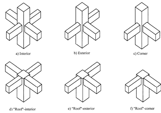
*SEFP Consistent Design**Pile Design**Doc No: 10-00-CD-0007**Date: April 16, 2018* 1.1. FUNCTION OF JOINT Beam-column joint must transfer the forces, such as moment, shear and torsion, transferred by the beam to the column so that the structure can maintain its integrity to carry loads for which it is designed. Another function of the beam-column joint is to help the structure to dissipate seismic forces so that it can behave in a ductile manner. 1.2.WHY DO WE CARE During an extreme seismic event, the code-based structure is expected to maintain its load-carrying capacity for gravity loads even after the structure deforms into inelastic range so that it does not pose any life safety hazard. Hence, the joint can go through significant degradation of strength and stiffness, and if it fails in shear, or anchorage, the life-safety objective of code cannot be achieved. 1.3.CONSEQUENCES OF FAILURE 1.4.THINGS TO CONSIDER FOR BEAM COLUMN JOINT Longitudinal bars of beams, or slab, must be able to develop their yield stress, so that the beam/slab can transfer moment to joint. It means that longitudinal bars must have adequate development length for hooked bars. This implies that the size of the column must be such that bars can develop their tensile forces. If bars can transfer moment, they can also transfer shear as far as monolithic construction is concerned. The shear strength of the joint must enable the transfer of moment and shear through it. The joint should be Constructible: Congestion of reinforcement is the main concern. 1.5.DESIGN SHEAR FOR BEAM COLUMN JOINT The design shear for beam-column joint depends upon the relative strength of beam and column at the joint. For the joints part of the special moment resisting frame, the shear force will be the one that corresponds to the development of hinge in the beam because the frame is required to satisfy strong column-weak beam criteria. If it is a knee joint, then joint area must resist the shear equal to the development of tensile force in the beam. The tensile force will be equal to the product of the area of tension steel, yield strength and the factor that represents the overstrength of steel rebar. If it is not a knee-beam-column joint then, the design shear of the joint will be algebraic sum of tensile force in the beam and the column shear. The column shear is the one that is required to keep the joint in equilibrium, i.e the shear corresponding to the development of the probable moment capacity of beams at the joint. For the joints not part of the special moment resisting frames, one needs to investigate whether the beam or column will yield first. For knee joint, if the column is weaker then the beam, the tensile force cannot exceed the moment corresponding to the development of hinge in column 1.6.THE JOINT: Definition and classification Portion of column within deepest beam that frames in to the column (ACI 352-02). ACI 352-02 categorizes joints based on the displacement-demand imposed by connected members. · TYPE 1 (Section 2.1.1 ACI 352-02) These joints possess limited ductility, and hence the connected members are designed for limited ductility. They are used in situations where ductility of structure is not a concern. · TYPE 2 (Section 2.1.2 ACI 352-02) These joints connect members which designed to have sustained strength under large deformations. Joints are also classified based on their location in framing system 1.7.THE JOINT: Design forces The joint is designed for the shear that results from attainment of the flexural strengths of members connected at the joint for type 2 joints. For type 1 joints, same principle is employed, unless the both members are overdesigned and the engineer does not expect both members, i.e. beam and column, to yield under design forces. 1.7.1. FLEXURAL STREGNTHS: TYPE 2 No strength reduction factor is used for computation of flexural strength. Steel stress is multiplied by factor of 1.25 for computation of flexural strength (3.3.4 ACI 352-02). For type 2 joints, the flexural strength of beams needs to be calculated only, as we do not expect the hinge-formation in columns; we will proportion the beam-column assembly of this joint as per strong-column-weak-beam approach. The slab reinforcement within the flange of beam must also be considered for computation of flexural strength of beam if the slab is integrally cast with beam and if the longitudinal reinforcement of slab is anchored (3.3.2 ACI 352-02). For interior connections, and for exterior and corner connections with transverse beams, the portion of slab to be considered as flange should be as per guidelines of section 6.3.2 of ACI 318-14. The effective flange width should not be taken less than 2 times the width of beam. For exterior and corner connections, without transverse beams, the effective flange width should be as per figures below (section 3.3.2 of ACI 352-02). The effective flange width for this case need not be taken more than 1/12th of the span of the beam. 1.7.2. FLEXURAL STREGNTHS: TYPE 1 For type 1 connection, similar procedure as discussed above should be used, if beams are expected to yield before columns. The stress multiplier factor for this type of connection can be taken as 1. The beam reinforcement, if any, as per section 24.3.4 of 318-14, with-in the effective flange width, must be included in determination of flexural strength in addition to the web reinforcement. If columns are expected to yield before beams, the nominal flexural capacity at beam-column joint should be calculated with due consideration given to the axial load on column. The beam moment in that case would be the one required to maintain equilibrium of the connection. If neither the beam, nor column, is expected to yield at factored loads, then the design shear of joint would be based on factored forces, moments and shear, at beam-column interface.
 1 point
 -
Modelling Issues/consideration in ETABS
G_Farooq reacted to Badar (BAZ) for a topic
I want to comment on some modelling issues in ETABS. Though some of these things are discussed elsewhere in the forum, I hope to extract some more useful conclusions. First thing is related to modelling the bending stiffness of flexural members, for strength level loads, that is representative of their condition near failure. The ACI code specifies the modifier of 0.35 on gross moment of inertia to represent its condition at yielding. Some people say that the factor should be multiplied by 2 to represent the stiffness of T-beam. This approach would be justified if you are not taking into the account the out of plan bending stiffness of slab. But, ETABS does include the out of plane bending stiffness if you have modelled the slab by using shell elements. So, a factor of 0.7 would overestimate the stiffness of your structure in this case, and will lead to under-design. If one has used the modifier of 0.35 in ETABS for beams in beam-slab floor system, then what value should be adopted for slab? It should not be 0.25, as this value has been specified for flat plates and flat sab floor system. If one is using some value of modifier for out of plane bending stiffness on shells, then the share of the bending moment in beams will be reduced accordingly. This approach is correct if one will be providing the reinforcement in column strips of slab. But, if you are providing reinforcement in slab in the direction perpendicular to supports only, i.e. beams, as is the general practice in Pakistan, then you are under-estimating the flexural demand in beams. Now, there is also a question of factors to be used while deciding the amount of reinforcement required in beams, columns and shear walls. If you are using factors 0.35 for beams and shear walls, and 0.7 for columns, then you are finding out the demand in members at the point of yielding, and this conforms to the code. But, this also means that the structure might experience unacceptable cracks widths. So, if you are using 0.35 for calculating the demand at strength-level forces, then you should also perform crack-control-check at service-level loads by using the factor of 1. If you are calculating the strength-level demand with a modifier of 1 for all structural members, after you have decided the location and the number of shear walls with modifier of 0.35, then you are overestimating seismic forces, as you are underestimating the time-period. But, the structural performance will improve.1 point
This leaderboard is set to Edmonton/GMT-06:00