Leaderboard
Popular Content
Showing content with the highest reputation on 08/05/16 in all areas
-

Shear Reinforcement In Etabs
Omer Ahmed reacted to EngrUzair for a topic
1. In the following explanation, I am referring to ETABS version 9.7.4, with active units of 'kip-in' for all quantities. You are probably using ETABS 13 or later version. In these later ETABS versions, systems of adoptable units have been improved, and new options of units have also been implemented. However, in order to understand the explanation given in the following, you will need to change active system of units your model to 'kip-in' for all quantities. Otherwise you might miss some important point. 2. In case of beams supported at both ends, shear force (& accordingly, shear reinforcement) is more near the beam ends, as compared to middle portion of the beam. For these beams, ETABS indicates shear reinforcement at 3 points along the beam _ at the start, at the middle and at the other end of beam span. If the beam is not subdivided into smaller parts, shear reinforcement value would generally be larger at both ends, as compared to that for the middle portion of the beam.(Beam in your attached image is indicating the similar results.) 3. Calculation of required stirrup spacing is similar, to that described for the ties in case of columns in my earlier post. 4. Upto which distance, what stirrup spacing is to be provided depends upon the shear force distribution along the beam, as will be clear from shear force diagram for the controlling load combination. This spacing will however subject to relevant provisions of ACI 318-08 Chapter 21, depending upon the earthquake zone or design category of the area in which your structure is located. 5. Now referring to the beam shown in your attached image, the value shown in the middle (0.1000), indicates maximum required shear reinforcement applicable to middle portion of the beam, whereas the other two values (0.1521 & 0.1351) are the maximum required shear reinforcement, to be placed at the relevant beam portions adjacent to supports (columns) on the relevant ends. In case your lengths in 'inches', and shear reinforcement in in 'sq.in/in.' units, you may calculate required stirrup spacing, similar to column tie spacing discussed earlier, keeping in view relevant ACI requirements. 6. For exact detailing of the 18 ft span referred beam, following further information is required: a. Overall Beam size (width & height) b. Image showing required shear reinforcement values, after changing the active units to 'kip-in' for all the structural parameters, similar to ETABS 9. It would be better & simplify the detailing a lot, if the beam is subdivided into 4-equal parts, before analysis. c. Earthquake zone or seismic design category of the area in which the structure is located. c. Structural frame system used (OMRF, IMRF, SMRF, etc.) d. Minimum reinforcing bar size used for flexural reinforcement of this beam e. Preferable bar size for stirrups (Normally #3, or #4 bars are used). Regards.1 point -

Shear Reinforcement In Etabs
Hussain Abid reacted to Juli for a topic
Very good explanation.. But it's for column tie. Now can you please explain this term for beam shear reinforcement? For a beam, shear reinf value is shown at 3 locations, so is it also same as Av/s ? and also then which should be the distance long of 3 locations? I mean please explain from a etabs output of beam shear reinf result. I am attaching an image of 18 ft beam which etabs is showing the shear reinforcement value in sq-in at 3 locations, now detail the shear reinf for this beam and make the detailing of only shear reinforcement. Thanks in advance.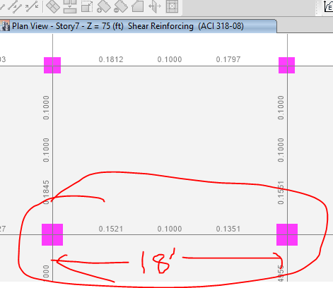 1 point
This leaderboard is set to Edmonton/GMT-06:00