

Rahulkld
-
Posts
25 -
Joined
-
Last visited
Content Type
Profiles
Forums
Events
Posts posted by Rahulkld
-
-
34 minutes ago, waqar saleem said:
In a room space of 10-6 x 10⁻⁶ what different intensities you will be applying ? for washroom area you can apply different load than room area.
That is what I want. and I have found solution thanks for your concern.
-
7 minutes ago, waqar saleem said:
Read this discussion
That's only half of my question and I have already read that.
-
What is the difference between : Live, Reducible Live and Roof Live in Etabs 2016?
Can I apply live of different intensities in a single slab like image below. As rooms has live of intensity 2KN/M2 but passage and Toilet has 3KN/M2. There are beams only connecting columns no intermediate beam. Thanks
-
On 6/1/2017 at 8:35 PM, Ayesha said:
I agree its ambiguous and design practice varies across different firms. Reasons provided are you are just and like you said this has been discussed elsewhere at forums too but there is no clear path.
I wonder what other people have to say about this.
Base located at the ground in that case.
- Ayesha and Ali Sufyan
-
 2
2
-
Finally I got it. It's only available for ACI codes.
-
20 minutes ago, BAZ said:
For newer version, go to Design --------> Concrete Frame design --------> View/Revise Preferences
Sorry Sir but still can't find to turn on alert.

-
1 hour ago, BAZ said:
Select the seismic design category by going to the "options" drop down menu.
Can't find Sir, Please help me find.
-
I want to learn performance based design. Please suggest me some best sources to learn for free online.
-
On 7/29/2014 at 6:50 PM, BAZ said:
Ratio of flexural capacity of Beam/column is computed to preclude the formation of plastic hinges in columns for obvious reasons, refer to section 21.6.2 of ACI 318-11. Sum of flexural capacities of column at a joint should be 1.2 times the capacities of beam framing into the joint in particular direction. Etabs alerts user when the ratio exceeds; if it does not alert, it means either you are ok, or you have not activated corresponding seismic category (I think it calculates for category D E & F) for which this capacity needs to be computed.
When capacity is exceeded, we can increase the size of column, or reduce the size of beam, or play with reinforcement of members. It has nothing to do with redistribution of moments; If both end of column will yield, during a seismic event, in a particular story, structure will most probably collapse. In a frame, that is resisting lateral loads, you cannot take away the ability of beam to develop negative moment; if you do not provide top reinforcement, it will not be called a moment resisting frame, and will not resist lateral loads..
Sir how to activate the feature for alert of exceedance of D/C ratio
-
Another solution can be reduction of no. of meshing. I think size of meshing depends upon boundary conditions also if I'm not wrong.
-
38 minutes ago, EngrUzair said:
What was the cause of the problem?
Please share for the information of others.
Regards.
It was problem with incorrect local axis assignment at 2nd floor cause of multiple edits, I made a mistake.
-
43 minutes ago, Ayesha said:
No, I have never seen this before.
Finally figured it out, thanks for concern.
")
-
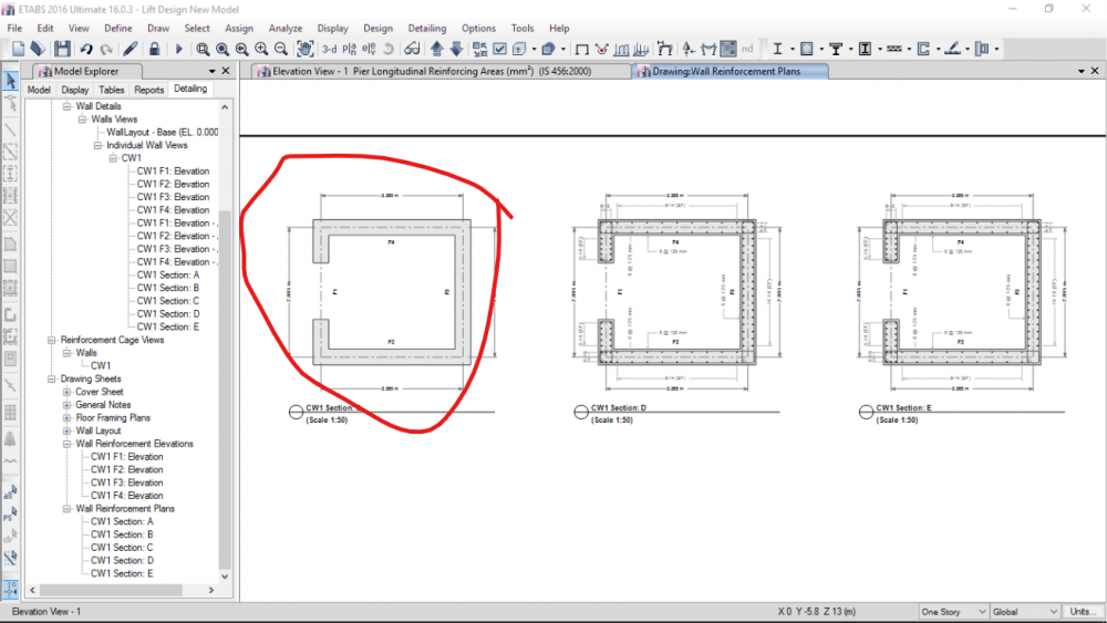
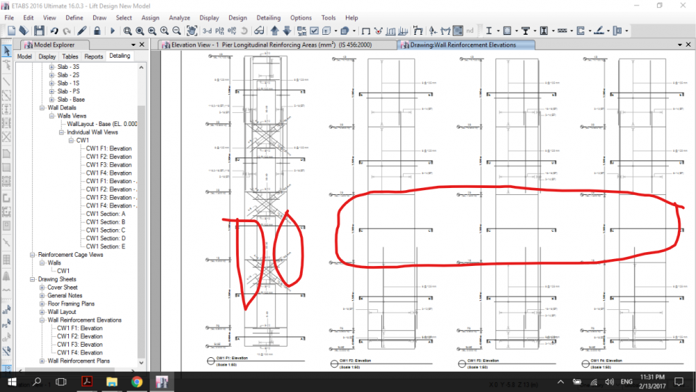
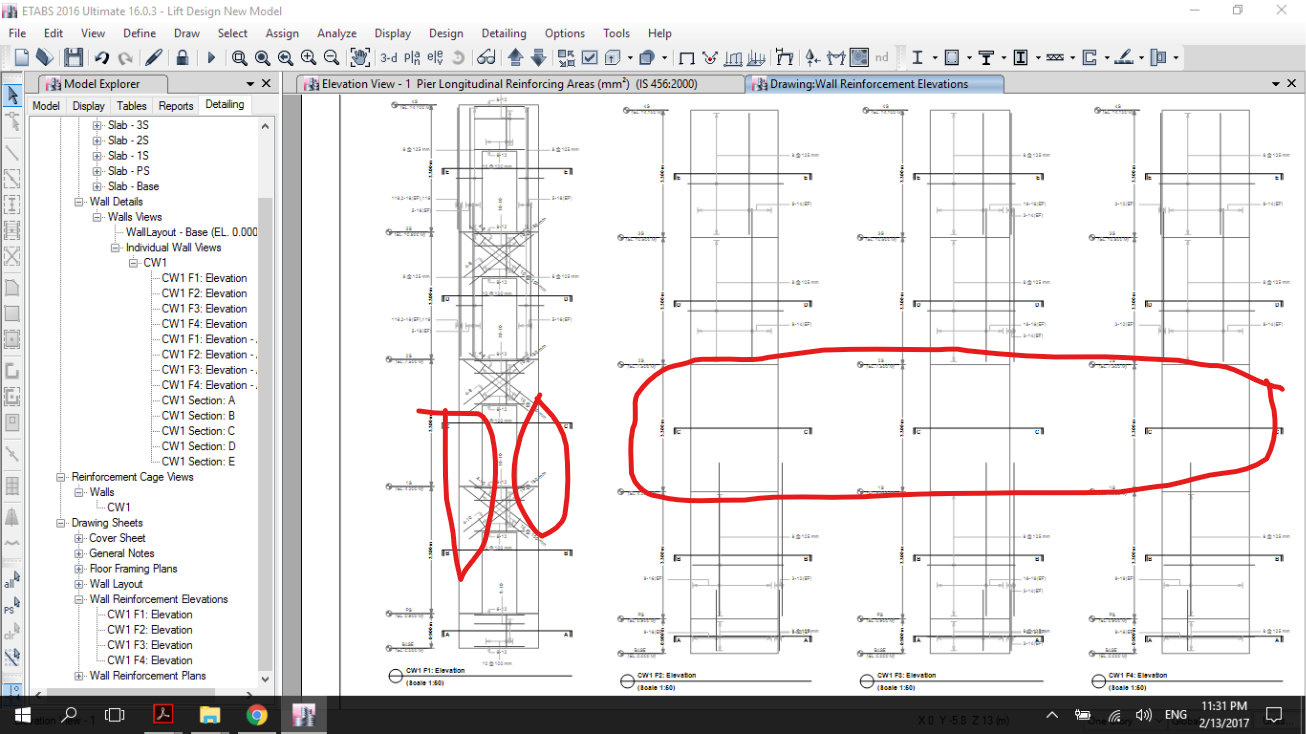
I'm trying to design a 4 storey lift in ETABS but while running detailing, rebar details for 2nd floor doesn't show up neither in elevation nor in section. Have anyone else faced such issue? What might be the problem?
-
8 hours ago, UmarMakhzumi said:
It is a very good question. I was in a similar situation recently but I separated my models. Wonder how do softwares consider that..
I got it sir. The mode shapes of two structures that are not connected to each other are independent. That's the reason ETABS not show the mode shape animation of both buildings at once. If you whant to evaluate the interaction of two buildings that are close to each other (e.g. the damaging contact during a seismic event), a dynamic modal analysis is not the way, this is a non-linear problem. A way to assess this issue is connecting both structures with gap elements and performing a nonlinear time history analysis.
-
Thank you sir. This forum is by far one of the best forum I'm in.
-
44 minutes ago, Saad Pervez said:
Which version of ETABS?
It's ETABS 16.03.
-
Hello everyone, I tried modelling two buildings which are close to each other in ETABS. When i tried to see time period at different modes. Etabs animated one building only for a particular mode. How does Etabs deal with such models? How can I see the animation of both building at once???
-
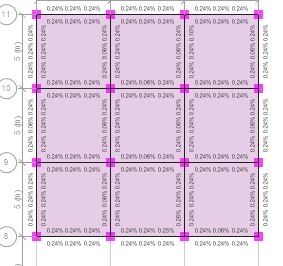
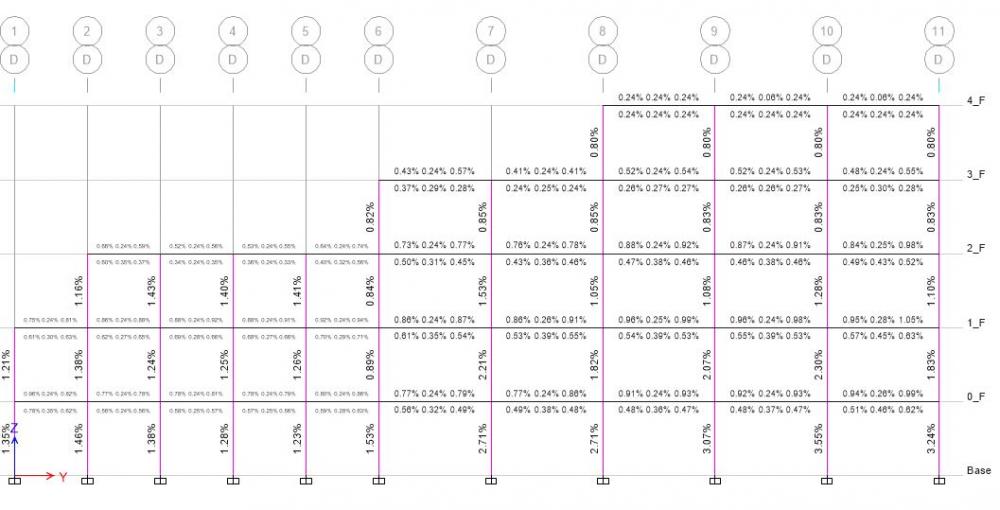
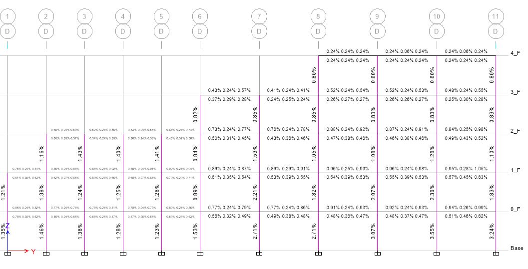
@EngrUzair thank you sir. For your reply. Sir kindly please refer me some document that I need to understand Modal Mass Participation Ratio table better in ETABS. I got below attached output. What might be complications. Also below outputs are appropriate??? As you can see beams near lift failed and one at the corner also failed.

-
On 1/7/2017 at 1:44 AM, Mehdi_ said:
As you know, we are forced to convert the ETABS results to executive drawings. This is a time consuming job. Is there any software that accept ETABS outputs and generate drawings? Specially for a reinforced concrete structure.
I think with Autocad Structure Detailing(now discontinued by autodesk last version was 2015) you can save a lot of time. I don't know if it accepts ETABS results but yes you can easily draw structural details and also get quantity of reinforcement. Also you can use Revit if you have already created your model in it. Hope that helps.
-
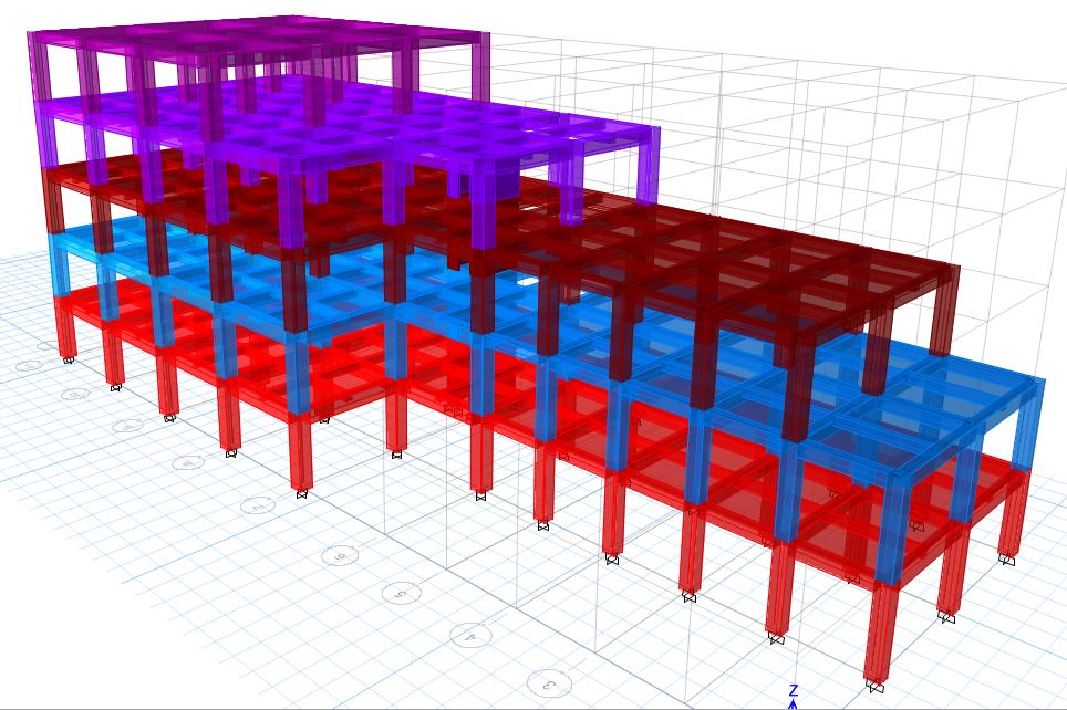
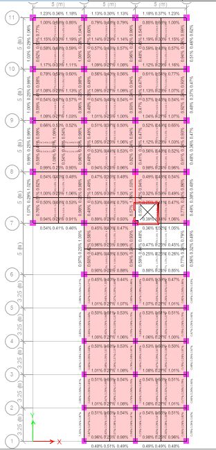
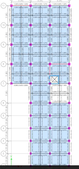
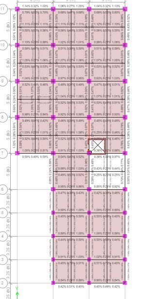
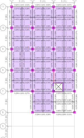
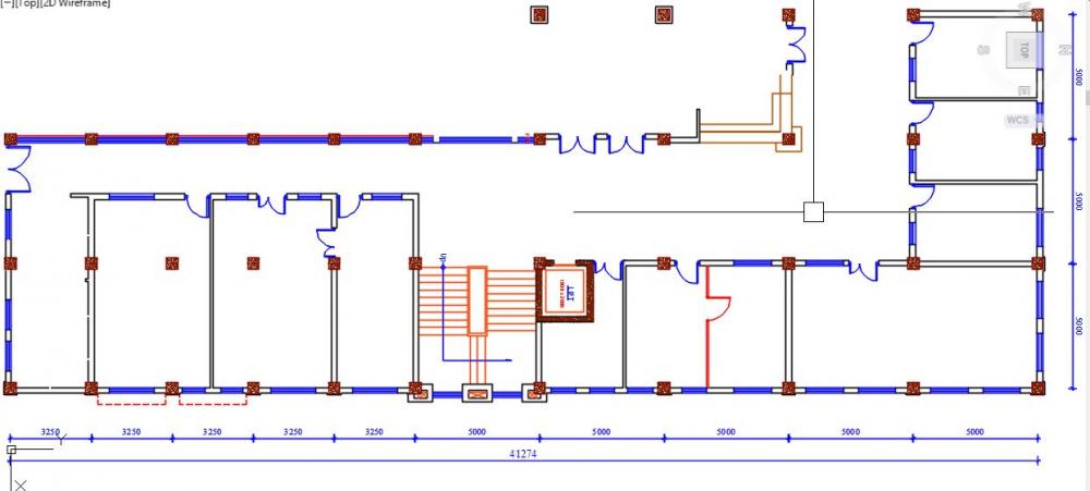
I tried designing a L shaped building(attached imaged) but it has torsional irregularity. How to counteract for that? Details of my material property and sizes are below. The beams(5m span) kept failing how can I design it.
Material: M20 concrete, Fe500 Rebar
Size: Column 500mm*500mm, Beam 500mm*400mm, slab 130mm
Load: Live load 4KN/m^2
Dead: Wall loads (9" and 5")
Staircase load was transferred to beams and lift was modeled in it's place.
The shorter part of "L" shape goes upto 5 stories(one with 5m*5m span) while on longer side(with 3.25 m* 5m) goes upto 4 storey.
-
Is there any tutorials or references to design and analyse brick masonry in ETABS/SAP2000???
-
Thank you very much sir. Thanks for your time and effort.
-
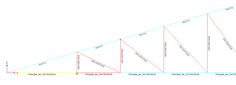
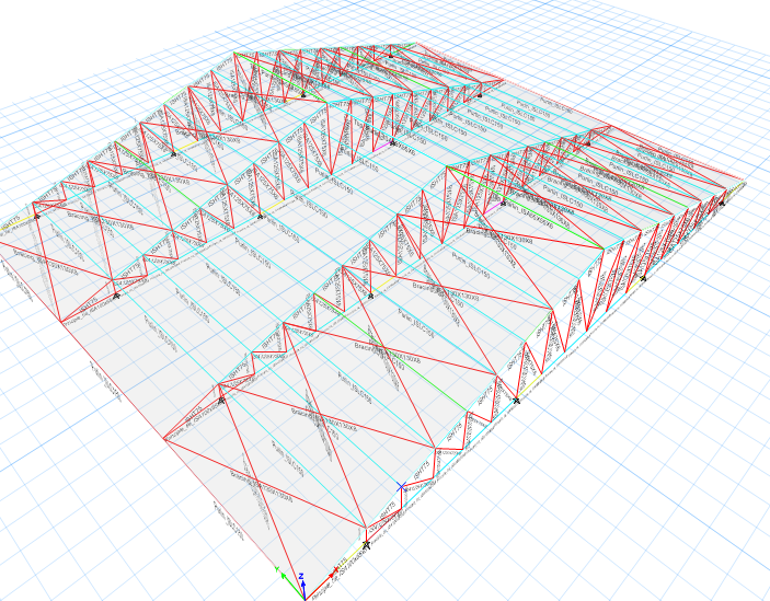
Thank you very much sir. I have another problem. I'm modelling steel for the first time, could you help on that also. The span of truss 19.15m *19.15m and I'm trying to model it. Sir, is there any document related to modelling of truss in ETABS. I'm following Indian Standard for design. This is my first attempt and most of the members failed. Thanks.

-
Can any one please help me with resources they have for designing Steel roof truss and Rcc column joint? Also if there is any references available for modelling such structural joints in ETABS? Thanks


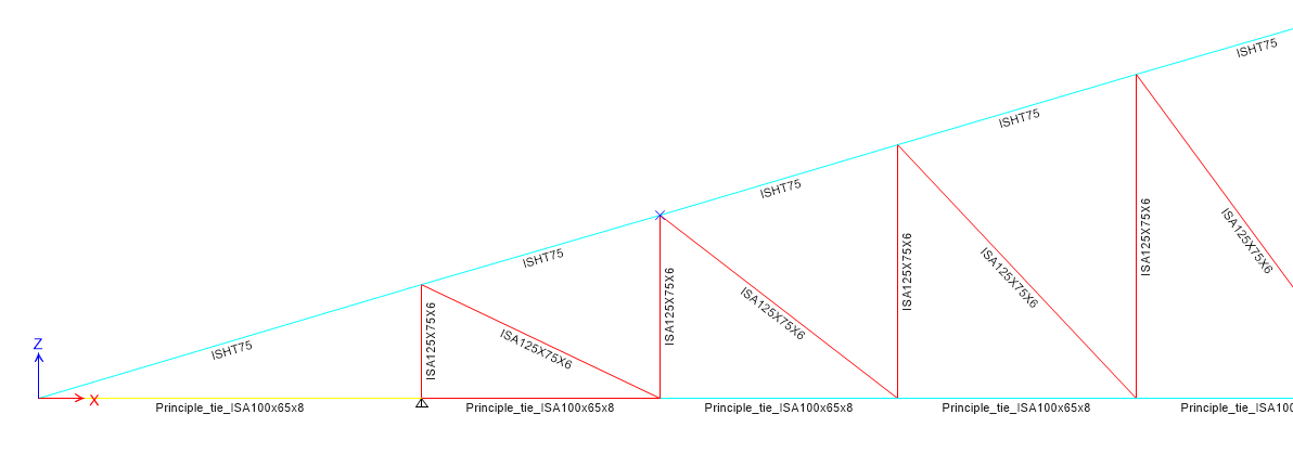
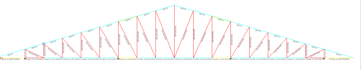
Truss member failing
in Steel Design
Posted
Hi everyone!,
I'm trying to design a shed of truss span 85', I have experimented with many different types of trusses. A problem that is common among most of them is failure of member near eaves. Does anyone know how to solve this issue? (*Eaves height is 24' and I can't put any member to support truss.)