
Badar (BAZ)
-
Posts
518 -
Joined
-
Last visited
-
Days Won
280
Content Type
Profiles
Forums
Events
Everything posted by Badar (BAZ)
-

Modelling Steel Truss with Overhang on ETABS
Badar (BAZ) replied to sochtheking's topic in Steel Design
Check your supports. What type of supports have you assigned? Have you assigned any end releases? -
I have a vague idea on how to approach it. But, yo should ask this question to some one in academics. Most of the practicing structural engineers do not need to do this in their projects; if you dot not do something often, then that concept goes away after period of time. Vague Idea for a particular mode: mass matrix x acceleration matrix + stiffness matrix x displacement matrix = 0 You can get mass, acceleration and displacement data for a particular mode and then work out stiffness matrix. I am not sure if it will be helpful or not.
-
Yes! Needless to say: cracked. One also need to specify the source of reinforcement as well via "cracking analysis options".
- 1 reply
-
- 2
-

-

-
Slab parameters for Open Grid Steel Flooring in ETABs
Badar (BAZ) replied to Osama Anwar's topic in Seismic Design
One do not start to develop basic understanding by working on a actual structure from the start. If you are at that stage, then you must have studied engineering mechanics, internal distribution of stresses in cross-sections for a particular external force, strength of materials, strength of cross-sections for a particular demand, and methods to estimate the distribution of forces in connected members meant for a structural behavior. If you are not designing the open floor itself, and your intention is to investigate the girders and columns; and to do that, you want to use area elements so that you do not have to apply gravity loads manually, then you need to ask yourself: Is my floor one-way or two-way? Can my floor transfer moments to supporting members? Do I want to model the self weight of the open floor through the use of area elements? For one way distribution, you could use deck slab or one way load distribution option. For two way action, add thin shell area elements. Second point: You can do that by setting a very low value of E, as well as releasing the rotational restraints at the ends of slab panel. Third point: Select appropriate thickness for a particular unit weight. -
Slab parameters for Open Grid Steel Flooring in ETABs
Badar (BAZ) replied to Osama Anwar's topic in Seismic Design
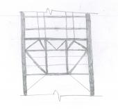
You seem to be approaching your modelling without clear and basic understanding of what constitutes as structural system in this kind of floor. What I see, when I look at this picture is: a floor in which loads are carried directly by beams, which in turn transfer the forces to girders; beams are laterally braced by cross-members. So, you need to model your beams and girders with line elements. And why would you take your modulus of elasticity as 0.00001? E is responsible for providing stiffness. If E is 0, it means do not have any structural member! I am sure that is not the case. -
Column development length in Raft Inward or Outward
Badar (BAZ) replied to Hamza Irshad's topic in Concrete Design
Yes, surely the mechanics of force transfer makes the hook redundant if development length is available. Code's language also suggests the same; the have used the phrase " if hooks are required...". -
Column development length in Raft Inward or Outward
Badar (BAZ) replied to Hamza Irshad's topic in Concrete Design
Yes, it has been prescribed for structures falling under seismic design category (SDC) D, E or F; these buildings are detailed to achieve higher ductility. The detail achieves higher ductility, so no need to do bend the column-longitudinal bars towards the centerline if ductility demands are low (structure need to satisfy the ACI 318 guidelines pertaining to SDC A,B and C for those). -
Column development length in Raft Inward or Outward
Badar (BAZ) replied to Hamza Irshad's topic in Concrete Design
From the seismic point of view, the former is recommended by the code (ACI 318-19). See the attached: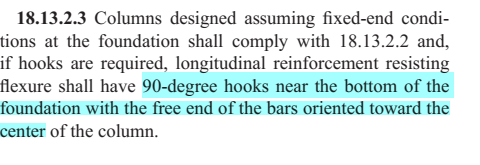
-
I am not able to grasp your predicament. Why would you want to make the spacing of negative and positive reinforcement the same?
-
You should detail the side as per the maximum demand on either side.
-
I think you are not getting his point. He is saying that if you allow column strip deflection to be 39mm as per L/240 criteria of the code, then that deflection will be translated to a value of 52mm at the mid span of middle strip. Explanation: For 39mm deflection, the slope of the deflected slab will be 9.3/2/.039 = 119.5 (about 1 in 120); and based on that slope, the midspan deflection will be about 12.46/2/.120 = 51.9mm. If possible, can you share how are you calculating your long term deflections of two way slab panels?
-
Read it again, you will change your your mind. Read the note 1 of the ACI's table 8.3.1.1 (318-14) meant for the guidance regarding the minimum thickness for non-prestressed slabs.
-
For the panel 2, I would go to table 7.9.2c of ACI 314R-11. The size of panel 2 will have to be determined from the outer most columns. Panel 1 is a "cornel panel".
-
The purpose of structural analysis, as Graham Powel puts it esoterically and with simplicity, "is not to get an exact simulation of behavior ..... the goal is to get demand/capacity ratios that are accurate enough for decision making". The exact analysis is not required for engineering problems, and it is not possible as well. For most RC slab-beam systems, the slab is only required to resist gravity loads. For gravity loads, you do not need to do ELF. The coefficients method of ACI 314R-11 will do the job even with its limitations. Same is true for one-way panels; you can use coefficients in ACI 318. For academic purposes, you can model your floor system in SAFE or can get the results for ETABS as well, as it can do design of slab as well. In actual practice, the level of investigation and scrutiny put on a particular structural member depends on the importance of the structural member in overall structural system. In your case, RC floor is the structural member with most load paths. It can transfer loads in ways unimaginable by most structural engineers. It does not warrant a detailed scrutiny unless it is acting as s transfer member at podium levels of a tall building.
-
STRUCURAL PLANNING / STRUCTURAL SCHEME
Badar (BAZ) replied to shazeb mirza's topic in General Discussion
Combination of following: intuition, observation, reading and talking about it. -
STRUCURAL PLANNING / STRUCTURAL SCHEME
Badar (BAZ) replied to shazeb mirza's topic in General Discussion
Reliable load path serves as a guide when deciding about the structural framing. -
Best University For MSc. Structural Engineering
Badar (BAZ) replied to Engr. Arslan Raza's topic in Students Zone
I agree with this statement with a slight modification: "until unless you work with some competent engineers and challenge yourself with technical problems on bigger projects" which challenge your pre-existing pool of knowledge. But that statement covers the development of competency of individual. In order to land a job which pays well, this is not enough at all. The MS degree has a huge advantage. A MS degree from a university of good standing in US, UK, Canada, AUS, New Zealand makes it easier for you to acquire a job at a company of international repute, and you are paid much better than the others as well. In Gulf, one will routinely come across adds which requires that the applicant must be registered as professional structural engineer (like CEng, MIStructE) in an internationally recognized regulatory authority (mostly UK). These are the people which pay almost twice to the people that satisfy their requirement. The requirement is simple, they pay to the privileged ones. This criteria of hiring anyone who is registered with a particular organization ( mostly Institute of Structural Engineers, UK) gives undue advantage; but, it is convenient for recruiters. In most cases, the one who is registered with Institute of Structural Engineers, would have got his Masters from there as well. Any one who has got the job (especially in Structural engineering) in western firms based in Gulf without the MS from above mentioned countries, count your self extremely lucky. -
Location of Base for Seismic Design.pdf Read the attached document. You initial design should not alter too much by incorporating the concern of third party in your model.
-
Pick Up Columns - Column Connection to Slab
Badar (BAZ) replied to Muhammad Hashmi's topic in General Discussion
You need to follow the guidelines of chapter 17 of AC318-14/19 or equivalent sections from older versions of the same code. Assuming, you do not have tension in the column, your post installed rebars must have enough embedment to satisfy the limit states corresponding to steel failure, concrete pry out and concrete breakout failure modes. -
Stiffness Modifiers for Pick Up Columns
Badar (BAZ) replied to Wajahat Latif's topic in Concrete Design
Idea is to stop the beam form transferring the negative moment to column. It is applicable at all levels. The longitudinal reinforcement of column does not effect. If I understood your situation correctly, there is no need for pick-up column to go beyond the landing slab at each level. -
Stiffness Modifiers for Pick Up Columns
Badar (BAZ) replied to Wajahat Latif's topic in Concrete Design
You do not need any complicated detail for that. Just leave the top bars without hook in beam-column joint. -
sub frame analysis --manual vs etabs results
Badar (BAZ) replied to d.malan9's topic in Software Issues
By joint translation, you mean that the manual calculations were based on the assumption that frame can not move side ways? Anyways, for practical purposes, this is not a significant difference. -
There are typical details of reinforcement, which can be found in various detailing manuals, that the design engineers follow around the world. They do not normally check development length for typical/usual member sizes with usual/ conventional loadings, instead they follow those reinforcement details. The critical section is the section with maximum tensile stress. For most beams or flexural members, it is the face of column or support. For this particular case, you can treat the wall-end as simply supported. But, there are other ways to develop the reinforcement such as mechanical anchorages (headed bar) or welding with end-plates. As you can see in your attached diagram, the length of hook is not considered by American codes. Some codes do consider them explicitly. For American codes, any length beyond 12db does not contribute.
- 12 replies
-
- 2
-
-
-
- hooks
- reinforcement detailing
- (and 1 more)
-
Stiffness Modifiers for Pick Up Columns
Badar (BAZ) replied to Wajahat Latif's topic in Concrete Design
Yes, it is. You can also release rotational restraint at the the end of landing beam. -
Multi-tower building with common podium in Etabs
Badar (BAZ) replied to Wajahat Latif's topic in Seismic Design
ok.