Our Picks
Top content from across the community, hand-picked by us.
Performance Based Seismic Design
Howard Roark posted a topic in General Discussion,
I am interested in performing "Performance Based Design" for a 20 story building.
I'll be performing "Non-Linear Static Pushover Analysis" for my model. Until now, I have decided to go with "Displacement Co-efficient method". I will be using ETABS 2017 for performing Pushover Analysis. While assigning plastic hinges, I have an option of using ASCE 41-17 (Seismic Evaluation and Retrofit of Existing buildings". I would like to know what would be a better estimate for relative distances for plastic hinges in case of beams, columns. Any input concerning assignment of hinges to beams, columns and shear walls is highly appreciated. Normally it's taken 0.05 and 0.95 or 0.1 and 0.9. What's your opinion on this?
Secondly, it would be great if someone can recommend me a book or some good source to understand how to characterize building using performance levels. Any sort of help is appreciated.
I have recently graduated and joined a structural design firm, so kindly guide me, considering me a beginner.
-
-
- 2 replies


Beam Column Joint
Badar (BAZ) posted a topic in Journal/ Articles/ Tutorials,
1.1. FUNCTION OF JOINT
Beam-column joint must transfer the forces, such as moment, shear and torsion, transferred by the beam to the column so that the structure can maintain its integrity to carry loads for which it is designed.
Another function of the beam-column joint is to help the structure to dissipate seismic forces so that it can behave in a ductile manner.
1.2.WHY DO WE CARE
During an extreme seismic event, the code-based structure is expected to maintain its load-carrying capacity for gravity loads even after the structure deforms into inelastic range so that it does not pose any life safety hazard. Hence, the joint can go through significant degradation of strength and stiffness, and if it fails in shear, or anchorage, the life-safety objective of code cannot be achieved.
1.3.CONSEQUENCES OF FAILURE
1.4.THINGS TO CONSIDER FOR BEAM COLUMN JOINT
Longitudinal bars of beams, or slab, must be able to develop their yield stress, so that the beam/slab can transfer moment to joint. It means that longitudinal bars must have adequate development length for hooked bars. This implies that the size of the column must be such that bars can develop their tensile forces. If bars can transfer moment, they can also transfer shear as far as monolithic construction is concerned.
The shear strength of the joint must enable the transfer of moment and shear through it.
The joint should be Constructible: Congestion of reinforcement is the main concern.
1.5.DESIGN SHEAR FOR BEAM COLUMN JOINT
The design shear for beam-column joint depends upon the relative strength of beam and column at the joint.
-
-
- 4 replies

Comments/Observations regarding modelling in ETABS
Badar (BAZ) posted a topic in Journal/ Articles/ Tutorials,
*Doc No: 10-00-CD-0006*
*Date: May 06, 2017*
Some of the observations made during extraction of results from ETABS (v 9.7.4), for design of reinforced concrete members, are being share in this article.,
1) Minimum Eccentricity
ETABS always considers the minimum eccentricity for selecting the design moment of columns irrespective of the probable behavior of the column, whether short or long column. See section 10.10.6.5 and its commentary of ACI 318-08 which deals with minimum eccentricity of long columns. You should always check the design moments that ETABS uses for columns if you want to bring down the cost of construction.
2) Unbraced/ Braced Preference
ETABS always performs analysis of frame as if it is un-braced. You should investigate if the storey under consideration is braced, or un-braced (10.10.5.2), and decide appropriate design moments of columns.
3) Time Period
ETABS has a tendency to select a time period of the building that is considerably less than the value obtained by the approximate method, Method A, of the section 1630.2.2 of UBC 97. To quote the FEMA 451 document: ''Because this formula is based on lower bound regression analysis of measured building response in California, it will generally result in periods that are lower (hence, more conservative for use in predicting base shear) than those computed from a more rigorous mathematical model". So, there is no need to use the value of time period that is lot less than Ta. One should always check the time period used by the software; ETABS can overestimate the seismic force by more than 2 times.
Visit the forum link to read the complete article.
Link: http://www.sepakistan.com/topic/2300-commentsobservations-regarding-modelling-in-etabs/
-
-
- 0 replies
Minimum Reinfocement Criteria For Crack Control
abdulqadeer29 posted a topic in Concrete Design,
So according to above statement , should we follow 0.60%, to be on more safe side??
-
-
- 12 replies
First South Asia Conference on Earthquake Engineering (Karachi)
Fatima Khalid posted a topic in General Discussion,
This email is an invitation for the participation in the First South Asia Conference on Earthquake Engineering (SACEE-2019) which will be held on 21-22 February 2019 in Karachi, Pakistan. This conference is the inaugural event in this series of conferences which has been constituted under the auspices of South Asia Earthquake Network (SHAKE). The organisers of the conference include NED University, University of Porto, University of Fuzhou, University Roma Tre and Institution of Engineers Pakistan. The conference website can be visited at http://sacee.neduet.edu.pk/.
Please note that world leading earthquake engineering experts have confirmed their participation in the conference. These include Prof Abdelkrim Aoudia (Italy), Prof Alper Ilki (Turkey), Dr Amod Mani Dixit (Nepal), Prof Bruno Briseghella (Italy), Prof George Mylonakis (UK), Prof Khalid Mosalam (USA), Prof Humberto Varum (Portugal) and many others. The presence of these distinguished experts allows you to exchange your work/issues with them and discuss possibility of any future collaboration. Please note that participation in the conference is strictly based on registration. Early registration in different categories at reduced rates are available till 10 December 2018. Please visit the conference website to see the details and the link for registration.
If there are any queries, please do not hesitate to contact the Conference Secretary at the following address
Prof. Muhammad Masood Rafi
Conference Secretary- SACEE-2019
Chairman
Department of Earthquake Engineering
NED University of Engineering & Technology Karachi, Pakistan.
Phone: 0092-21-992-261261 Ext:2605
Email: rafi-m@neduet.edu.pk
-
-
- 1 reply
Minimum reinforcement For Precast Pile
Dr Yueh posted a topic in Foundation Design,
-
- 1 reply
ETABS model for factory building
Palash Engr posted a topic in Concrete Design,
-
- 1 reply
Underground water tank base slab as a foundation
Fatima Khalid posted a topic in Foundation Design,
I have columns which are conflicting with the underground water tank as shown in figure.
So I have decided to make underground water tank base slab as a footing for column. So I import etabs model to safe and just take uniform water load on base slab and point load from columns.
This is the residential house. The BC is 2tsf. But SAFE is showing tension on the base slab and the thickness from punching is 30''. I believe that thickness is too high. What can be the error? Is this approach is correct for design base slab of ugwt to carry load of two edge columns?
-
- 11 replies
Safe Iterative Uplift Analysis
asadishaq posted a topic in Software Issues,
-
-
- 15 replies

Shear wall design
farooqbro posted a topic in Concrete Design,
i am facing problems in shear wall design .what are the pier and spandral ?what will be the difference when we assign pier or spandral? without assigning these the shear wall design is incomplete .
i am taking about etabsv16
someone have document about shear wall design plz provide it
thank you
-
-
- 13 replies

Forum Update
UmarMakhzumi posted a topic in Website Announcements/ Problems/ Login/ Registration Issues,
The forum has been updated today with a lot new features.
You can find the list of all the new improvements by visiting this website.
Some highlights are:
1) Improved Search Features
2) Emoji
Emoji support is now available in all editors.
Do check out the link posted above for the complete list.
One additional announcement that I would like to make is that with reference to last forum update post (read below), @Rana and @BAZ are forum Admins now. I think it was important to do as it brings more transparency for the forum and also helps spread the responsibility. The forum belongs to the members so it never made sense for one person to be Admin,
As always, feedback is much appreciated.
Thanks for taking the time out to read this update.
Cheers!
-
-
- 3 replies
Crack Width For Watertight Requirements According To ACI
WR1 posted a topic in Concrete Design,
---------------------------
Normal structures
---------------------------
1. ACI 318-95 based on statistical method of Gergely & Lutz 1968 limits Z based on exposure. We are calculating crack widths here. (Normal structures)
2. ACI 318-99 proposed limiting the spacing and removed actually calculating the width and also removed the exposure conditions. For example for beams and one-way slabs s (in) = 540/fs -2.5cc or in other words limiting the fs=0.6fy (For normal structures)
3. ACI 224R-01 references method 1 and 2 above and 3 european codes.
The most confusing part is the table in which Nawy suggests 0.1mm crack width for water-tight structures. The whole document is for normal structures except this line. And people are following this line and refer to this document for water tight structures. I mean its just a suggestion and by the way this method 1 is obsolete now since ACI 318-99 (see point 2 above).
---------------------------
Water tight structures
---------------------------
1. ACI 318-08 states clearly that for watertight structures ACI 350-06 codes should be used.
2. ACI 224.4R-13 also specifically states that for watertight structures walls in section 7.4, we should use ACI 350-06.
3. ACI 350-06 for water tight structures does not recommend calculating a number for crack width but rather limiting max steel stress in bars to be 20k ksi or fs=0.33fy for normal conditions.
---------------------------------------------------------------------------------------------------------
To sum it up,
Philosophy of crack width control is not to calculate probable crack widths but to limit the max stress in steel bars.
For normal structures: fs=0.6fy and for water tight structures fs=0.33fy
-
-
- 3 replies
Diaphragms
Shariful Islam posted a topic in Concrete Design,
I want to know the use of diaphragms in etabs. i discus many people who are use etabs but i can't get justified answer about the application of etabs.
I read the Technical reference of Etabs, where they write about Diaphragms. i get two type of diaphragms (plate or shell and joint or beam).
My question.
1. When do i use Shell diaphragms (if floor present )
2.When do i use joint diaphragms ( grade beam level where no slab are provide)
NB: Diaphragms use to transfer the lateral load to the resisting element ( frame such as column. beam,shear wall)
-
- 2 replies
Pile Design
UmarMakhzumi posted a topic in Journal/ Articles/ Tutorials,
This article is intended to cover design of piles using Ultimate Limit State (ULS) method. The use of ULS method is fairly new for geotechnical design (last decade). The method is being used in multiple countries now (Canada, Australia etc). The following items shall be discussed:
Overview
Geotechnical Design of Piles (Compression Loads, Tension Loads and Lateral Loads)
Structural Design of Piles (Covering both Concrete and Steel)
Connection of Pile with the foundation (Covering both Concrete and Steel)
Pile Group Settlement
Things to consider
1. Overview
Piles provide a suitable load path to transfer super-structure loads to foundation where shallow foundation are not suitable - this can be due to a number of reasons like existing space constraints or suitable soil strata is not present immediately below structure. Other uses can be to meet design requirements like to have reduced settlement etc.
This article shall cover the use of straight shaft cast-in-place concrete piles and straight shaft driven steel pipe piles. There are a number of additional piles types like belled concrete piles, precast concrete piles, screw / helical steel piles etc but the discussion to choose a suitable pile type is not in the intended scope of this article. The article is intended to discuss design requirements for straight shaft piles only (both concrete and steel) . The aforementioned topic about pile selection is a very diverse subject and requires a separate discussion on its own.
Click on the link to read the full article.
-
-
- 10 replies
Pile Design For Machine Foundation
Mohammad Yaseen Yousafzai posted a topic in Foundation Design,
I ll appreciate your help in terms of guidance & provision of notes...
Thank you..
-
-
- 36 replies
Quote from J.G. MacGregor
Badar (BAZ) posted a topic in General Discussion,
based on an elastic theory which assumes that structures display a linear response throughout their loading history, ignoring the post-yielding
stage of behavior. Current design practice for reinforced concrete structures is a curious blend of elastic analysis to compute forces and moments, plasticity theory to proportion cross-sections for the moment and axial, load, and empirical mumbo-jumbo to proportion members for shear.
From the book "Design of Concrete Structures with Stress Fields" by A. Muttoni, J. Schwartz and B.Thurliman.
-
-
- 0 replies

9th International Civil Engineering Conference (ICEC 2017), December 22-23, 2017, Karachi, Pakistan
Fatima Khalid posted a topic in Shout Box,
NED University of Engineering & Technology in collaboration with Institution of Engineers Pakistan (IEP) is organizing 9th International Civil Engineering Conference (ICEC 2017) on December 22-23, 2017 at Karachi, Pakistan.
The congress details are available at its website www.neduet.edu.pk/icec
Also attached is congress flyer for information and dissemination among your peers.
Abstracts submission deadline has been extended till October 31, 2017.
Please click on the link to see the full description.
-
-
- 0 replies
Picked By
UmarMakhzumi,Construction/Cold joint location in RC Column/walls
EngrJunaid posted a topic in General Discussion,
Is it mandatory to do column concreting upto the soffit of the beam in a single pour ?
What code says about the construction/cold joint location in column ?
Majority of the contractors are pouring the column concrete upto the soffit of the beam (full height of the column), some contractors leave the column height about 9" to 12" below the beam level and then fill this 9" to 12" column height with the beams & slab concreting. On one site column concreting was stopped at the mid height and the remaining half was filled on the next day.
Thanks
-
- 6 replies
Washigton Accord !!!
Waqar Saleem posted a topic in Shout Box,
Congratulations to Engineers, PEC has become full signatory of Washington Accord, what are the benefits to Pakistani engineers for this agreement.
Regards
-
- 3 replies
P-Delta & Selenderness Effects in ETABS
Ali Shan posted a topic in Concrete Design,
1. If we run P-delta analysis in ETABS, then should we ignore stiffness property modifiers for beams and columns? I have heard that if we perform P-delta analysis and apply stiffness modifiers at the same time then the moment magnification process is doubled...?
2. ETABS considers selenderness of a column by applying moment magnification factors. If we run P-delta analysis also, does it mean that the selenderness of column is being over-estimated? I mean once the moments are magnified in P-delta analysis process and again through moment magnification process?
Please help me understand the software myth and clarify above confusions.
-
- 1 reply
Development Length Of Standard Hooks
Waqas Haider posted a topic in Concrete Design,
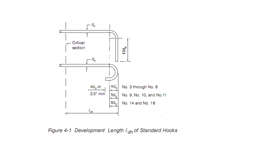
According to ACI 12.5.2,
development length for fc' = 3000, fy=60000, for normal weight concrete and epoxy less reinforcement, The required development length comes out to be
for #3 = 8.2 inch
for #4 = 10.95 inch
for #6 = 16.42 inch
for #8 = 21.9 inch
And if in my case, ACI 12.5.3 is not fulfilled, it means now i have to provide ldh as mentioned above. ldh is STRAIGHT EMBEDMENT LENGTH + RADIUS OF BEND + ONE BAR DIAMETER as shown in figure attached. Now my question is, if in my case, main reinforcement of beam is of #6 and #4, minimum column size required will be 18 inch and 12 inch respectively. Lets say by any means, i can not select #4, #3 bars and size of column where bars are to be terminated is 12 inch, how to fullfil this development length???
-
-
- 11 replies
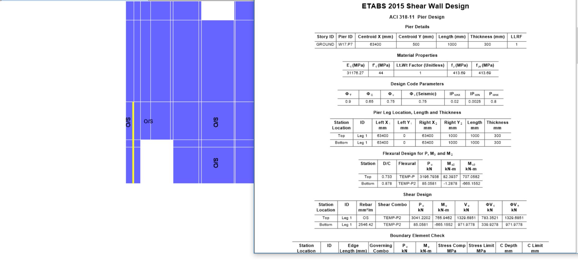

ShearWall - Temperature Design in ETABS
rummaan17 posted a topic in Concrete Design,
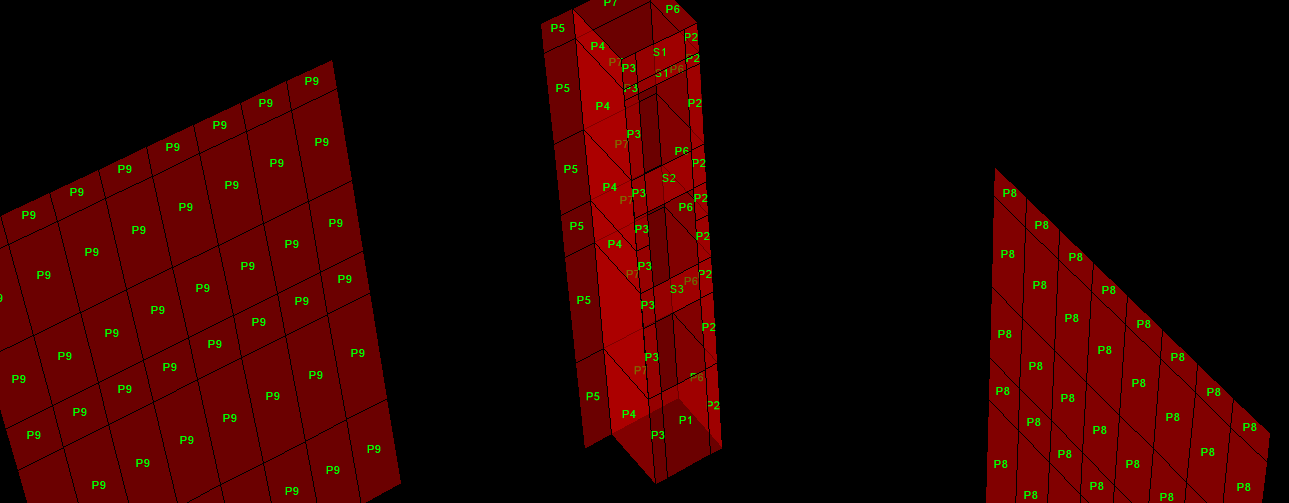
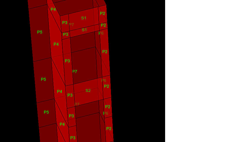
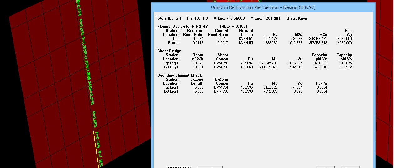
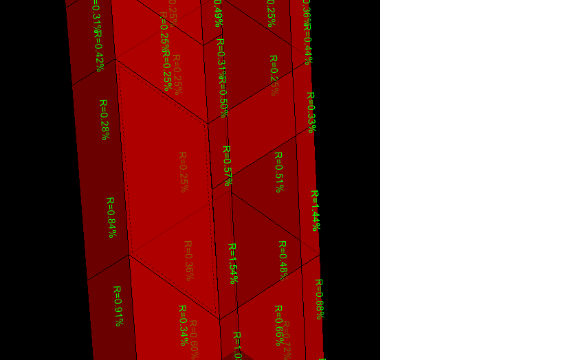
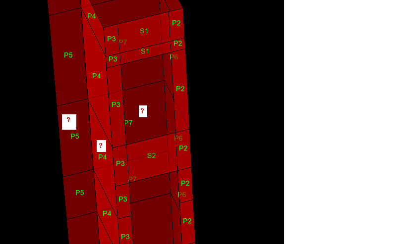
I am trying to design shearwalls through ETABS with temperature load applied over shell. At various location, spandral section fails in Shear due to temperature and piers (sometime in shear, mostly in flexure). (See Attached Image)
Certainly all the problem in Shearwalls are due to temperature. I don't want to increase cross section of spandral or pier at some location just due to temperature load case as it will appears non-uniform with rest of the wall.
I have seen stiffness modifier affect distribution of forces and also rigid/semi rigid daiphragm assumption.
Can anybody guide how to properly design the shear wall with temperature load applied in ETABS or share any similar experience. Thanks in Advance.
-
-
- 15 replies
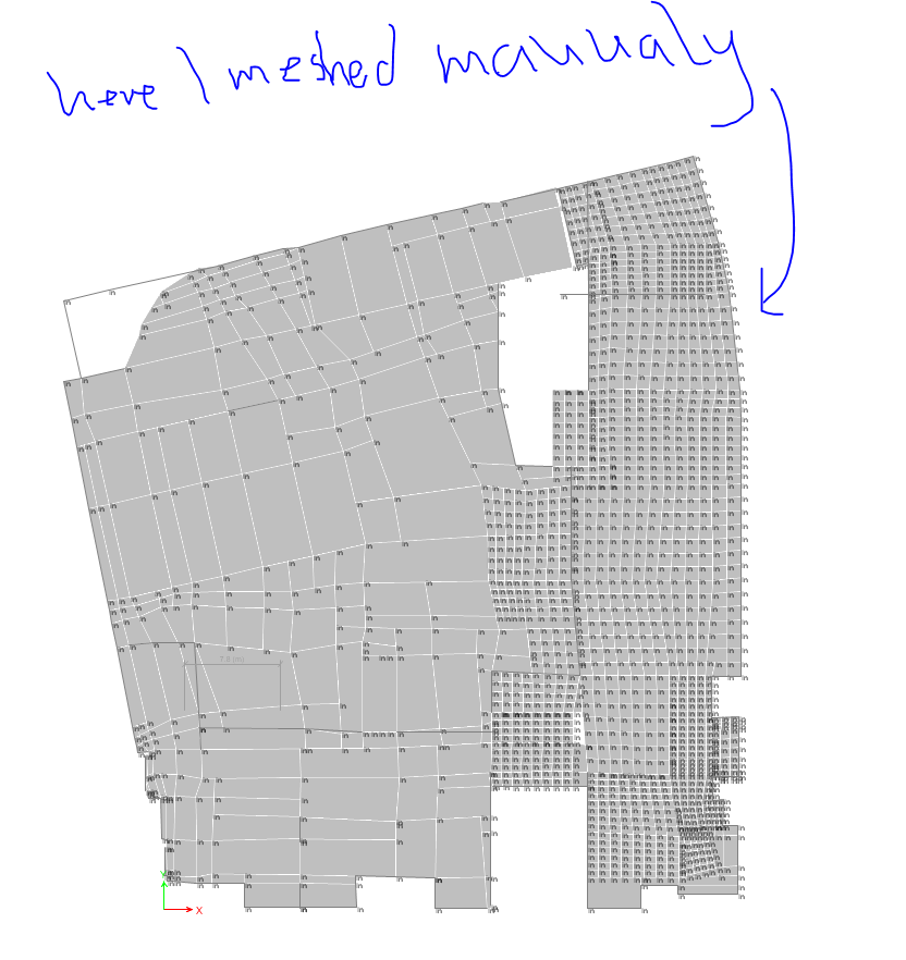
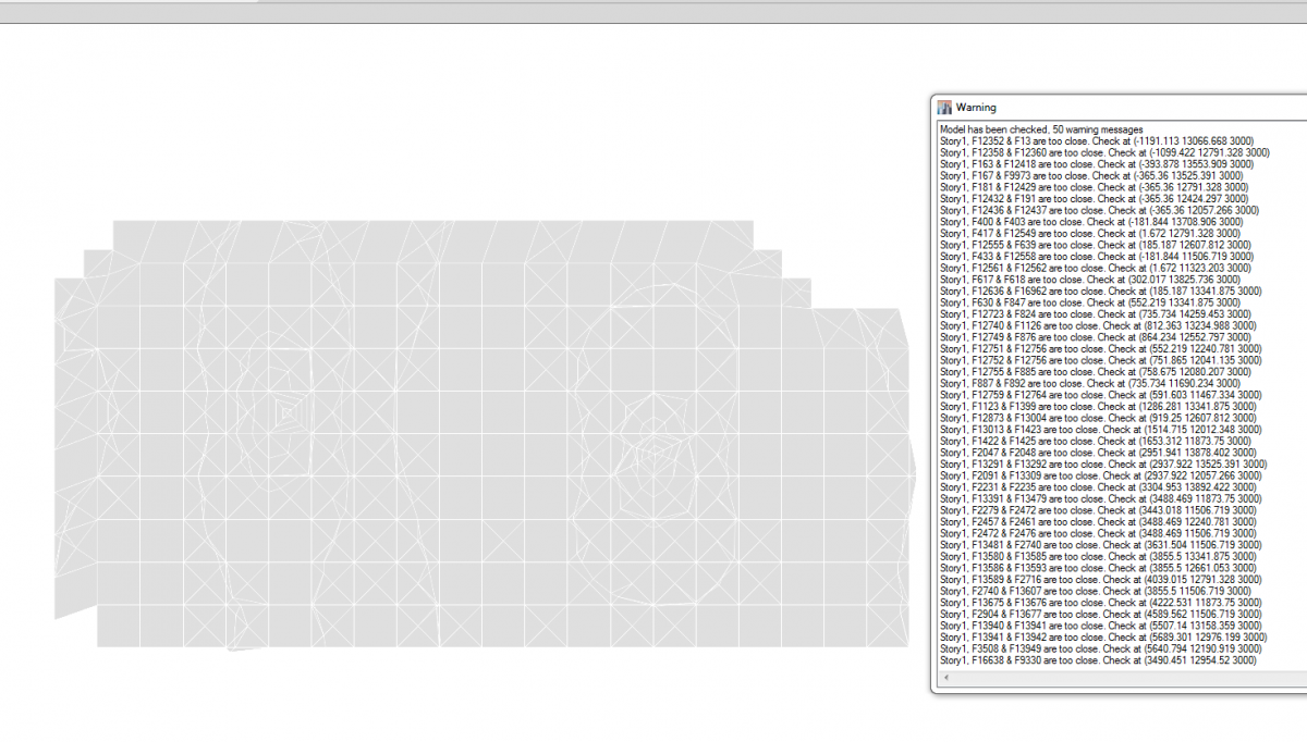
Etabs Manual Meshing Problem
mhdhamood posted a topic in Concrete Design,
I WILL LOOSE MY BRAIN FROM ETABS.
I DECIDED TO MAKE MANUAL MESHING FROM AREA ELEMENTS BESIDE EACH OTHER AND EVERY HING WAS FINE .
BUT AFTER DEVISION SAY 7*7 ELEMNTS FOR EVERY BIG ELEMENT AND MAKING ETABS CHECH..................THEN 500 ERROR MESSAGE THAT ALL ELEMNTS ARE CLOSE TO EACH OTHER. WHAT ARE GOING...... SOMEONE TELL ME PLEASE...... I WILL LOST MY WORK
-
- 6 replies
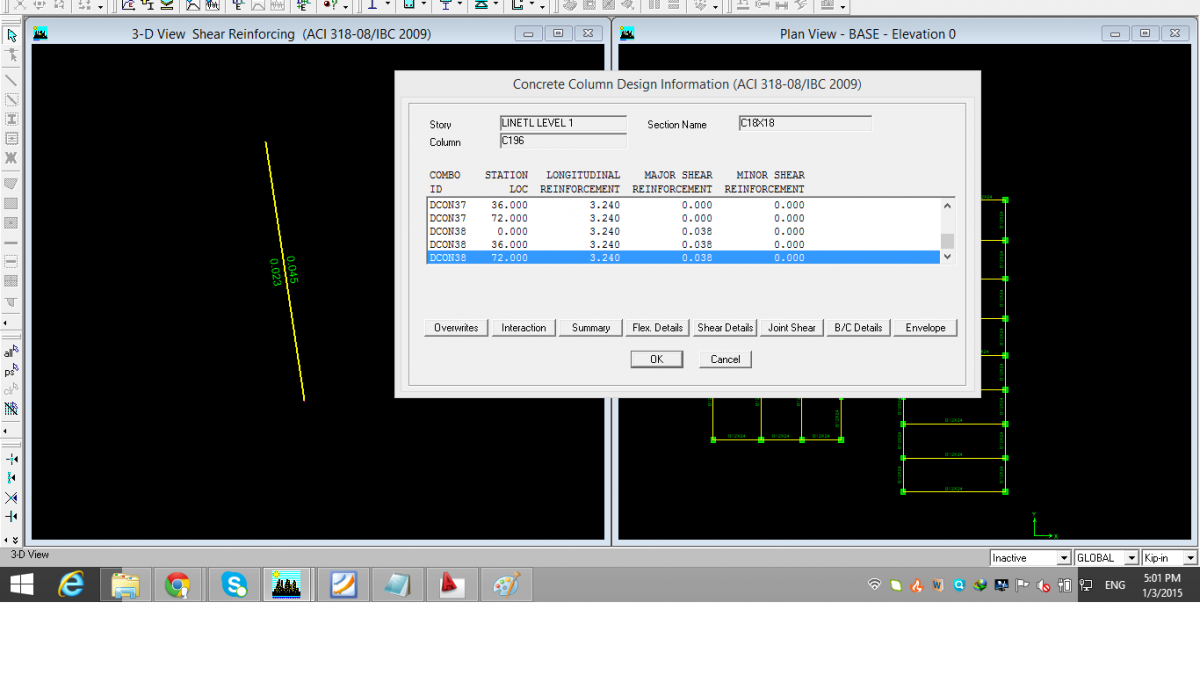
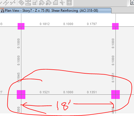
Shear Reinforcement In Etabs
Waqas Haider posted a topic in Software Issues,
I have just designed a frame structure with SMRF. The out put of shear seams weird to me. Column reports design shear Av/s as 0.045. (Images are attached). but when i right click the member, it must show me the most critical case HIGHLIGHTED AUTOMATICALLY. But it highlights load combo 38 (auto-generated combos have been used) which reports Av/s as 0.038. And 0.045 value is at combo 32. Is their any logic behind it?? More over how to interpret this Av/s?? means 0.045 in kip-in units means what? How can i convert this into spacing??
-
-
- 9 replies
Response Spectrum Analysis in ETABS
saleem khan posted a topic in Software Issues,
-
- 7 replies
-
Recently Browsing 0 members
- No registered users viewing this page.
-
Popular Contributors
Nobody has received reputation this week.
-
Topics
-
-
Posts
-

By mohammed ishaq · Posted
what is our ultimate goal by making reduction in members stiffnesses in softwares ?? i know the concept but i do not know the sense behind this in terms of the practical advantages will get after doing this and what will happen if we did not . -
By mohammed ishaq · Posted
hi engineers , May i know why we have to rely on meshing to govern our programe results and hence the design , if result is going to be affected by meshing how colud we get the accurate result for safe design ??? and to what limit can we depend on meshing ? -
 Just use excel. Make a simple worksheet listing bar dia, number, length for each element. Bar weight tables are available online. OR If its a building and you have the Etabs model. Run the detailer, it will give weight of steel required for each floor or member wise. Staad Pro also gives total steel weight and concrete volume for the model
 -
By UmarMakhzumi · Posted
W/Salaam, Do you know Python? You can use ChatGPT or any other AI platform to write code for python or any other language. It can probably create a visual basic script for you as well that you can use in excel. Thanks. -
 Assalam u Alaikum, I need a software for bar bending schedule and ultimately calculating the weight of steel. I am a structural engineer and this quantity calculation is not my field but I need it for some specific task. Can someone guide me which software free or pirated is available out there?
-

