WR1
-
Posts
985 -
Joined
-
Last visited
-
Days Won
286
Content Type
Profiles
Forums
Events
Everything posted by WR1
-
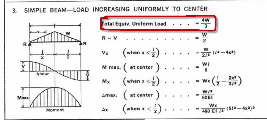
yar masla kia ha....ku preshan ho.....its simple...haroon...for one beam resting on 2 columns...make those columns straight..(like 3 spans of a beam) and use moment coefficient method....) it will solve your problem....beam col connection is between a fixed / pin option.... For Skype sorry I got busy in writing a book....pm me in this forum whenever u get free....ok? @waqar factors of 1.33 and 1.3 are used for ease to convert triangular and trapz loads to equivalent udl to calculate moments... Actually you can calculate moments without converting them to equivalent udl (this is just for ease)... For example look at picture 1 showing your triangular loads It states that "EQUIVALENT TOTAL LOAD = 4/3 of W = 1.33W" in kips but other formulas are given to calculate moments...you will see M = WL/6 where W is total load (W=0.5xLXW in kip/ft) so M = WL²/12 for simple beam having triangular load..ok now this factor of 4/3 or 1.33 is calculated so that both formulas yield equal moments....but as i have said...you can ignore this short cut and solve by your usual triangular loaded beam formulas... anyways...for your reference you can calculate exact moments for triangular loaded beam by formulas attached in above picture....for trapz loaded beam see the pic below... i hope it helps!
-
yes....no need for mass source where there is no EQ
-
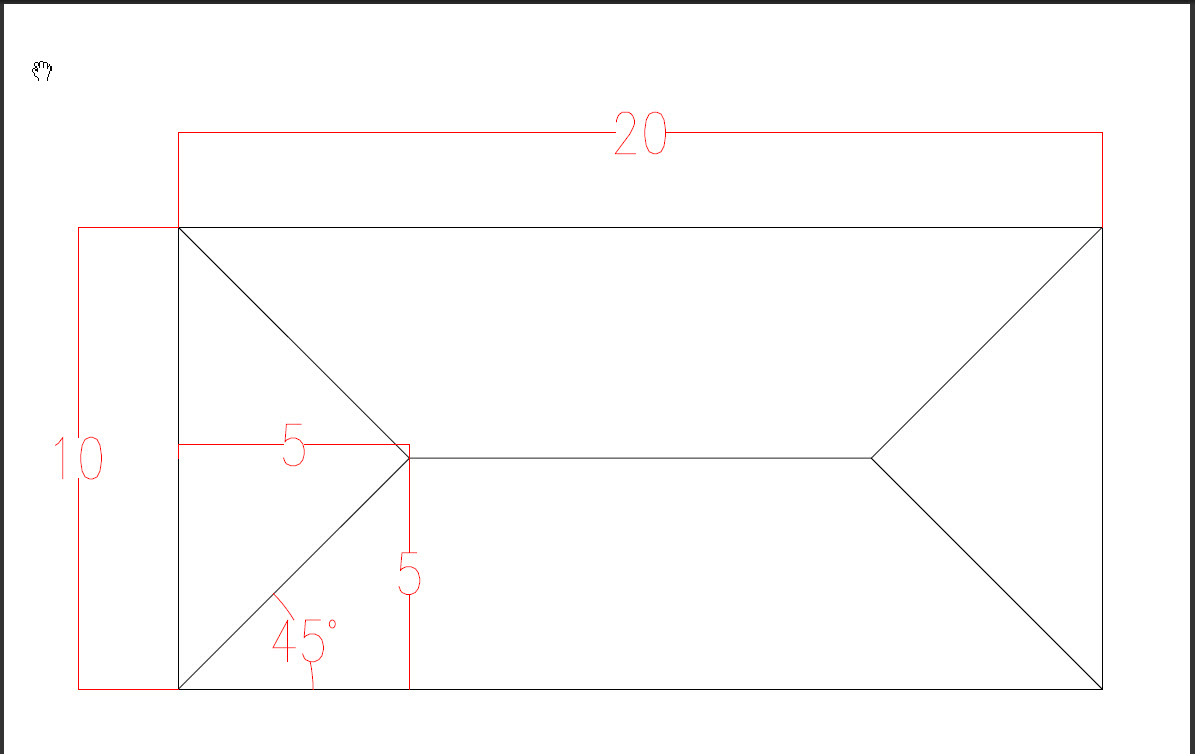
its clear from pic... etabs will do it this way even if the slab is 2000x10... for strictly one way loading...you can click "ONE-WAY" option in ETABS if you slab is supported by 2 sides only as in case of precase panels....you have to click "ONE-WAY" option otherwise your load transfer by 2 way method will be incorrect... but if you have solid slab supported on all four sides and even it is one-way (theoretically e.g. 20x10) it will be considered 2 way by ETABS, its more rational... but what i would do is to let ETABS do it, its way and I will increase the reinforcement by some margin in the longer beams.... for triangular loads (short side) : mulitply the intensity (w in kip/ft or kN/m) by 1.33, it will convert this loading to simple uniform loading over whole beam length...then use your conventional formulas to calculate moments and shear for trapezoidal loads use factor of 1.30. @waqar yes moment coefficients are not 1/24 and 1/12 but i said these are coefficients for fully fixed end one beam span....similary 1/11 or 1/9 etc coefficients in ACI 8.3 approximate method are also approximate....by engineering judegement and your experience you can solve quickly some beam by these methods...some times the factor is not even 12 rather may be 20....see the limitations in ACI 8.3 for the method...

-
what about skype? your basic ideas need to be corrected ......u will be ready in 2 hours for skype?
-
well u have membrane slab and you are meshing it? remove the meshing and see the results you will find 625 lb/ft on your longer and shorter beams for live load... (Display>Show Loads>Live) remember it will distribute load by 45 degree method you despite that your slab is 10x20 (1way and your short beams will carry nothing) but if you do it by 45 degree your short beams will also have 625lb/ft load for live loading... when your loading is okay then your shear and moments will also be ok.... you said results matched with moment distribution method...on ELEVATION 1 but not on ELEVATION A i think it should also match ...you have single frame 1 beam and 2 columns...just make the columns straight and you will have 3 span continous beam...thats it..solve it by moment distribtuion method...i hope you will get the desired results....ask again if you are still in difficulty!
-
well i just the image u attached....it should give you proper results as compared with moment distribution method.....you cannot get moment (+) by wl²/8...because its a continuous frame.....here idealize the beam as fixed end...and take the moment wl²/12(-) and wl²/24 (+) these factors 12 & 24 will vary depending upon the stiffness of the beam/column joint..if they are fully fixed then this formula will give u the required results... anyways, first of all make sure that.... 1) end offsets for all frames are = 0 (because you need moment at c/c of beam & col not at face or distance d as in design) 2) make sure no dynamic analysis is being done 3) make sure no earthquake forces are there 4) use same section to col and beam for equal stiffness, use square sections lets say 12 in x 12 in
-
fella, come on skype this evening....ok? waseemrana87 is my id
-
Help Needed Regarding Concrete Structure Designed In Etabs
WR1 replied to haro0n's topic in Software Issues
check different etabs topics in this forum and other internet sources... check answers by arshad khan here: http://en.allexperts.com/q/Civil-Engineering-1357/indexExp_18389.htm -
Help Needed Regarding Concrete Structure Designed In Etabs
WR1 replied to haro0n's topic in Software Issues
some more comments:- dont apply raft in your etabs model..export the reactions to SAFE and model raft there...or if you want to model it in etabs..then dont apply fixed supports..apply area springs according to your soil properties...in your model i have removed the raft... you applied PLATE option for RAFT..but you should be familiar with the differences between MEMBRANE, PLATE and SHELL... This time i have applied modifiers according to your approach...( inside frame section properties..) now you should not select the beams or cols and goto ASSING>FRAME>MODIFIERS...dont apply it again..otherwise it will be duplicated and etabs will multiply both values...i mean if you applied inside 0.25 and then from menu again 0.25 so it will consider 0.25x0.25 remember i have changed your slabs to MEMBRANE..so no need to apply meshing to MEMBRANE...also before designing your sections select sway ordinary as in your case the frame is not sway frame... still i didnt applied manual checks..you should do it your self...calculate the tributary area of any column and multiply by load..and see if your base reaction for that column is okay or not? check the loading of a beam manually and compare with etabs... calculate the moments of any frame on a grid by ACI 8.3 approx coefficients method and compare...or you can moment redistribution methid,,, now u must be thinking how hard struc engg...makes the life... my version is 9.7.4 so im attaching only text file..import it in your etabs model... good luck assignment_checked.zip -
sorry guyz i removed all links from 4 shared...and put it on my website... The link is: http://www.ranawaseem.com/2010/09/ubc-sesimic-calculator.html
-
its the seismic weight according to code. The load you put here will be used for Seismic calculations. This is W in IBC, UBC or other american codes... Select "From Loads" option and put all dead loads with factor = 1 and all live loads with factor = 0.25 this is to consider 100%dead loads + 25%live loads for seismic calculations....
-
try purchasing the lecture seminar dvd from skgosh for 185$ on post tension design of slabs
-
you are welcome
-
change your units to lb-ft as you know concrete density is 150 pounds per cubic feet = 150 pcf now w=mg according to physics...and g = 32.2 ft/s² so your mass will be = 150/32.2 = 4.658 lb remember to check your units....if in your case it is kip-in then weight = 150 lb/ft³ / 12³ / 1000 = 8.68E-5 kips/in³ (not just 8.68 as you mentioned in your question) similary mass = weight / gravity = 8.68e-5 / 386.4 = 2.246E-9 (because 32.2 ft/s² = 32.2x12 = 386.4 in/² as your units are kip-in) weight and and mass are not affected by compressive strength....
-
Base Shear, Eccentricity And Checks In Etabs
WR1 replied to abdulqadeer29's topic in Concrete Design
yar both will give you precise results....but do automatic meshing if and only if..you have regular building or floor or part of floor... otherwise do it manually in large chunks and you can mix both the techniques...make slabs regular by manual meshing then do it auto mesh...its ur choice... when you make automesh..just goto view options and turn on meshing option....you will see yourself..where the automeshing is causing problem.... for foundation...how can you remove shear walls....and design the foundation....ofcouse there will be much more reinforcement under your shear wall....its a lateral resisting element.....but there are some areas of higher concentration of stress...you dont need to take this in design...you can average it on a relatively bigger area.... -
Base Shear, Eccentricity And Checks In Etabs
WR1 replied to abdulqadeer29's topic in Concrete Design
it depends..if its very regular use auto..otherwise ur in trouble lolx -
Base Shear, Eccentricity And Checks In Etabs
WR1 replied to abdulqadeer29's topic in Concrete Design
1) What do you mean by eccentricity of the building? you mean the deflection of the building from lateral loads or you are talking specifically about seismic design? 2) Base shear is the shear force of the building from lateral loads. This shear is produces moments and other forecs in shear walls, columns and beams...when transferred to them by the diaphragm such as slab. 3) Check the total axial force or reaction of the building under dead load and live load..See if this is what you applied in your assignments? Calculate the ditributary area of a column and multiply by its loading and check the axial force in that column. Export the displacement tables under a combination or load case to excel and check the maximum deformation. Goto last analysis run log..it should never show you that the building is unstable and ill-conditioned.. Goto response plots in display menu to see the base shear plot of lateral loads..if there is strange shape it means you have supports in intermediate levels.. Check if there is tension in the walls under wind load..etc.. there are many checks to be performed to feel confident about the building. this level varies with each building and its importance and the level of knowledge you have... i hope it will help- 8 replies
-
- 2
-

-
- base shear
- building eccentricity
- (and 1 more)
-
but really sir WILSON is the man..mje mil jae to us ke pero me gir jaoun heheh
-
oh i c....well thanks for clearing the confusion...today i spent my whole day on this...thanks a lot...
-
ok thanks...i understand what u said...my building is not regular thats y im concerned with orthogonal effect..anyways...i have this confusion:- I understand that u cannot take both directions in one spectrum load case because it will be 100 and 100 which is not realistic.. but my point is why then CSI team has put this option in ETABS..they could have omitted u2 text box from there....there should be some reason why they put it?
-
First of all my apologies, if my question seems stupid because of my unfamiliarity with the topic. When defining response spectrum load case in ETABS, we have three directions; u1, u2 and u3. Lets assume the excitation angle = 0 and building principle direction is u1 So I will apply response spectrum function (per IBC 2006) in u1 direction by a scale factor. My question is why we don't apply u2 and u3 in the SAME LOAD CASE. My understanding is, according to WILSON in his book on STATIC & DYNAMIC ANALYSIS, CHAPTER 15. The response is calculated for each direction separately. Then this response is combined by different methods (CQC, SRSS etc) which is called MODEL COMBINATION. In CQC method response in 2 directions is assumed to be a portion of 1 direction means S2=a.S1 Where a = 0 to 1.0, recommended value is 0.50 to 0.85 I know in EQ building has only one principle direction. Although EQ can hit from any direction but there is always one major direction. or you can say major acceleration in 1 direction. Lets say u1. As in CQC method the response in other direction will be some portion of response in major direction. I also know that If we have equal spectra CQC is reduced to SRSS method which is independent from the excitation angle theta. My confusion is we will do MODAL COMBINATION (cqc or srss) only when we want to combine u1, u2 and u3 at the same time. But if we are applying only u1 in one response spectrum load case, then we DONT have to do modal combination. It is the same thing as in CQC S2=a. S1. Now in this case a=0. so S2=0. All we have is only response in u1 direction. Then in my building models what i do? include u1 and u2 both in one load case or in separate load cases?
-
I know in the code these modifiers are for lateral deflection. but then how would you justify the reduced moment of inertia after cracking? Are you talking about membrane slab which has no out of plane stiffness? Yeah in membrane the modfiers will not affect but in shell if you dont apply the modifers, the slab will carry all the moment. I just want to be more clear about the concept, because we apply modfiers in every model. and according to ACI we can use the same modifiers set for lateral and for strength design. (for wind serviceability the modifiers are multiplied by 1.4 in a separate model).
-
another thing. if you put the same modifiers for every thing like walls, columns, beams, floor etc..so the reduction will be uniform it will not affect the results. but if you make something stiffer and another less stiffer so you basically are creating differences in stiffness so is the difference in the moment that will goto these elements. like in this example i have applied beams = 0.35,0.35,0.35 (j,m22,m33) cols = 0.7,0.7 (m11,m22) slab = 0.25,0.25,0.25 (m11,m12,m22) walls = 0.7,0.7(m11,m22)
-
So just compare the two images, model having modifiers have less stiffness, so take less moment, that moment is distributed to other stiff elements. so the point is if you reduce the stiffness as in case of cracking, it will affect deflection as well as moments. so the reinforcement values depend upon the moment. I agree with you that in beam design formula, it depends upon b and d. Now this b and d are not with modifiers rather full values. But the moment which has to be used in this formual is less because of less stiffness due to reduction in modifiers.