.jpg.c0f3ad0ef57922aceb6ddba3017280bc.jpg)
Waqas Haider
-
Posts
190 -
Joined
-
Last visited
-
Days Won
17
4 Followers


Recent Profile Visitors
5011 profile views


Waqas Haider's Achievements
")
Newbie (1/14)
94
Reputation
-
 Mazhar Amin reacted to a post in a topic:
Deduction Of Overburden From Bearing Capacity
Mazhar Amin reacted to a post in a topic:
Deduction Of Overburden From Bearing Capacity
-
Nawaz Qasim reacted to a post in a topic:
ECCENTRIC LOAD IN ETABS
-
UmarMakhzumi reacted to a post in a topic:
Billboard Design
-
 Muhammad Hashmi reacted to a post in a topic:
ECCENTRIC LOAD IN ETABS
Muhammad Hashmi reacted to a post in a topic:
ECCENTRIC LOAD IN ETABS
-
Muhammad SAqib shah reacted to a post in a topic:
Spring Support- Modulus Of Subgrade Reaction
-
Ayesha reacted to a post in a topic:
Confined Masonry Guidelines Pakistan
-
Osama Anwar reacted to a post in a topic:
ECCENTRIC LOAD IN ETABS
-
SMAQ reacted to a post in a topic:
Spring Support- Modulus Of Subgrade Reaction
-
Vamshi Prasad reacted to a post in a topic:
Purpose of design strips in safe
-
Vamshi Prasad reacted to a post in a topic:
Design For Shear And Torsion Using Etabs
-
Top reinforcement is needed in isolated footing majorly for two reasons. 1) Due to negative pressure under some or whole part of footing. In part of footing where there is positive pressure, the footing is in complete contact with soil and tension is in bottom side of footing. But in part of footing where there is negative pressure the footing is no more in contact with ground. Either it is designed as it is (and reduced contact area is used for calculations) or it is made to become in contact with ground by help of over burden loads. In either case, the bending of footing is in such a way which causes tension of footing at top of foundation demanding top reinforcement in footing. Mostly top reinforcement is less than bottom reinforcement but for simplicity, if it is not affecting economy much same reinforcement can also be used for top and bottom. 2) Due to temperature and shrinkage control. Code says we can provide temperature based minimum steel either in one layer at center or at any face or we can divide total steel in two layers i.e. half at top face and half at bottom. According to Zahid Ahmad Siddique (Professor at UET Lahore) in his book concrete structures mentions it is better to provide temperature steel in two layers if thickness of footing increases 18 inch.
-
From engineering point of view, it is really very amazing to see a complete city builtup in water ways, in a lagoon. How did they make the foundation system of buildings completely all the time underwater? Really interesting article here is. It also explains some modern challanges to the city i.e. flooding due to raised levels of sea and an inteseting solution to this problem. https://sites.google.com/site/engineeringvenice/

- 1 reply
-
- 2
-
-
-
- piles
- foundation
- (and 3 more)
-
.thumb.jpg.700916fbc7ead330085e15745d0270bd.jpg) Waqas Haider changed their profile photo
Waqas Haider changed their profile photo -
I use etabs version 9.7.4 so i can tell u about importing plan from cad to etabs in this version. Define a layer in CAD for example GRID LAYER. then draw ur whole grid in this cad layer.. after you finish marking grid in cad drawing, save the file as DXF FILE instead of DWG extension. Please note that the insertion units of cad drawing (you can see insertion units by UN command) and in etabs while importing this grid must be same. One u saved drawing as dxf file. open new etabs model, delete existing grid, import file as DXF file, set units before importing the file in drop down manu. Select layer of Grid and import this layer. U will get your grid import. since there are a lot of grids usually in a cad drawing, it is better to shift whole grid before savin as dxf file into a new cad drawing with origin set 0,0,0. Copy grid from old drawing as a block into new drawing in desired layer, open new cad drawing, paste and put insertion coordinates as 0,0,0 Then explode the block and save file as dxf and import this file as said above. More over Perpendicular an inclined grids can be made in etabs but i prefer to go for importing grid because it is less time consuming and easy.
-
Assalam o alaikum, i m confused whether collectors and chords are only required in Flat plates/slabs or also required in beam slabs? because in beam slab we are having beams at perimeter of every panel and they can act as chords and for diaphragm bending and as collectors at junction of slab to shear wall. Usually, in seismic zone 4, i dont design diaphragm exclusively. i just design it as simple slab and design my beams in SMRF or Dual Frame in etabs. Also i m confused in excerpt from a document stating The Special Seismic Load combination is also indirectly identified in Chapter 18, Section 1809, Foundation Construction – Seismic Zones 3 and 4. 1809.3 Superstructure-to-Foundation Connection. The connection of superstructure elements to the foundation shall be adequate to transmit to the foundation the forces for which the elements were required to be designed. For instance, since Section 2213.5 Column Requirements specifically identifies the Ω0 factor, Section 1809.3 requires the column-to-foundation connection to be designed for a load combination which includes the Ω0 factor. What does it mean? In seismic zone 3 or 4, we need to design foundations for special seismic combos ALWAYS or only if we r having discontinuous system? The full document is also attached. Thanks. OmegaFactorDiscussion.pdf
-
Waqas Haider reacted to a post in a topic:
Beam deflection in Etabs
-
In manual calculation we do 2D analysis of structures using different method of analysis than stiffness method. So somewhat difference will always be there while you compare results of manual vs Etabs in Systems.. For individual elements, they are 100% same.... More over, be sure to make modifiers of slab to 0.0001 to nullify slab stiffness because in manual analysis, might be u are assuming only rectangular beam and applying line load to this beam. but in etabs you are modeling slab with beam making system a bit stiffer due to slab stiffness. If you will reduce slab stiffness to negligible value, than results will be near to each other. Still there will be some difference because we might be using force methods idealizing 2D structure while etabs performs 3D analysis using direct stiffness method.
-
Backfill load with backfill in negative slope
Waqas Haider replied to Waqas Haider's topic in Concrete Design
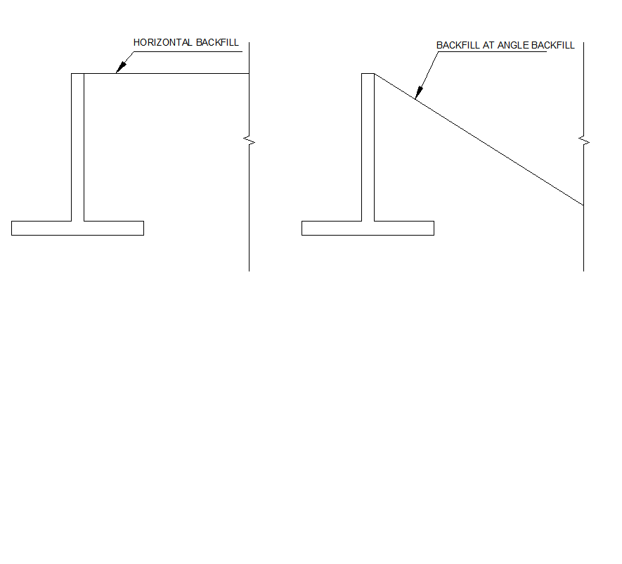
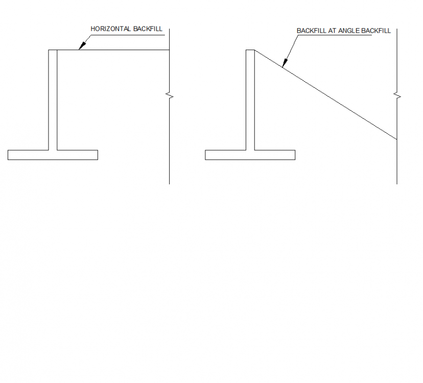
As per discussion with my senior in office, we have concluded that since soil slope angle is already lesser than angle of repose of soil, so soil will not slide to that slope. Wedge of soil will be exerting pressure on wall because at wall we are forcing soil to stand at larger angle than its angle of repose. So i was wrong than we should take lesser backfil load than total height. We should take ful height or at least the height of soil which cantilever heal is bearing.... This is what we think.. If we concluded wrong, kindly correct. thanks. -
Assalam o alaikum, If a retaining wall is retaining horizontal backfill, It will experience soil presure due to full height of backfill because we are forcing soil to retain at an angle larger than its angle of repose and hence failure wedge will cause force on full height. But if a retaining wall is retaining backfill having sloppy face( for insulation purposes lets say), then it should not experience the pressure due to full height in my opinion. Because soil is having slope on opposite side, (away from wall) and hence if a failure plan would occur, it will cause soil to slide away from wall, not towards wall. This is what i think. Pictures are also attached. In my case the wall height is 30 ft but it is retaining a backfill with slope. So i wonder if i should take load due to full 30ft height. I think i can take 25 ft height(or some other reduced value). Can any one guide me how to calculate backfill load due to such type of backfill? Thanks.
-
Waqas Haider reacted to a post in a topic:
IITK Articles about Seismic Design
-
Ads for Guests
Waqas Haider replied to UmarMakhzumi's topic in Website Announcements/ Problems/ Login/ Registration Issues
Yeah. I always use to amaze who is funding this website except you sir. It really need fiances, time and extreme effort to arrange and manage such a website having a good interface along with updating options of social world. It is really good sir. You have initiated a chain and it is really making change in Pakistani community of engineers who rely on internet a lot for learning. We try our level best to spread this forum as much we can. At end, heartily thanks to the moderators and all other members of the forum who are sharing their knowledge and time with people. Thanks. -
Waqas Haider reacted to a post in a topic:
Ads for Guests
-
Waqas Haider reacted to a post in a topic:
Ads for Guests
-
A very interesting and explanatory document along with example..... design of dome.pdf
-
Design For Shear And Torsion Using Etabs
Waqas Haider replied to Hasnain Khan's topic in Concrete Design
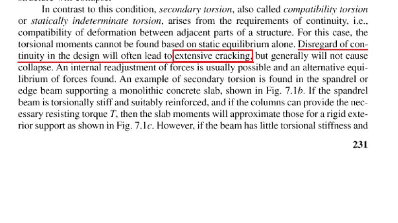
This is what i found in "Structural Concrete theory and Design by Nadeem Hussen" Here it also reports the same thing that we should design for torsion for atleast φ4λ Sqrt(fc ′) A2cp / Pcp Which is also specified by ACI that we can reduce our torsion upto phi.Tcr i.e. cracking torsion and not below this. Even if we neglect the remaining torsion for compatibility, we should atleast perform design for phi.Tcr or should at least provide minimum longitudinal and transverse reinforcemet for torsion. This is to control crack width to satisfy servicability. ACI, Nilson and Nadeem hussen all quote the same thing. Hence reducing the modifier upto such a little value is not good at start. At start we should go for a value of 1, 0.3 or any other suitable value which user think is small enough to release majority of compatibility torsion and will sustain only smaler torsional moments. After designing, if still some indeterminate beams are being failed, then for the specific beams we can reduce value unless we get Tu equall to phi.Tcr or a bit larger than that. Because putting Torsional modifier to 0.001 would not report any torsional reinforcement and hence adding no torsional reinforcement at all would cause excessive crack widths affecting serviceability of the structure. -
Building Joint Displacement/ Drift in Etabs
Waqas Haider replied to farooqbro's topic in Concrete Design
please go through this thread. Thanks. -
Waqas Haider reacted to a post in a topic:
Building Joint Displacement/ Drift in Etabs
-
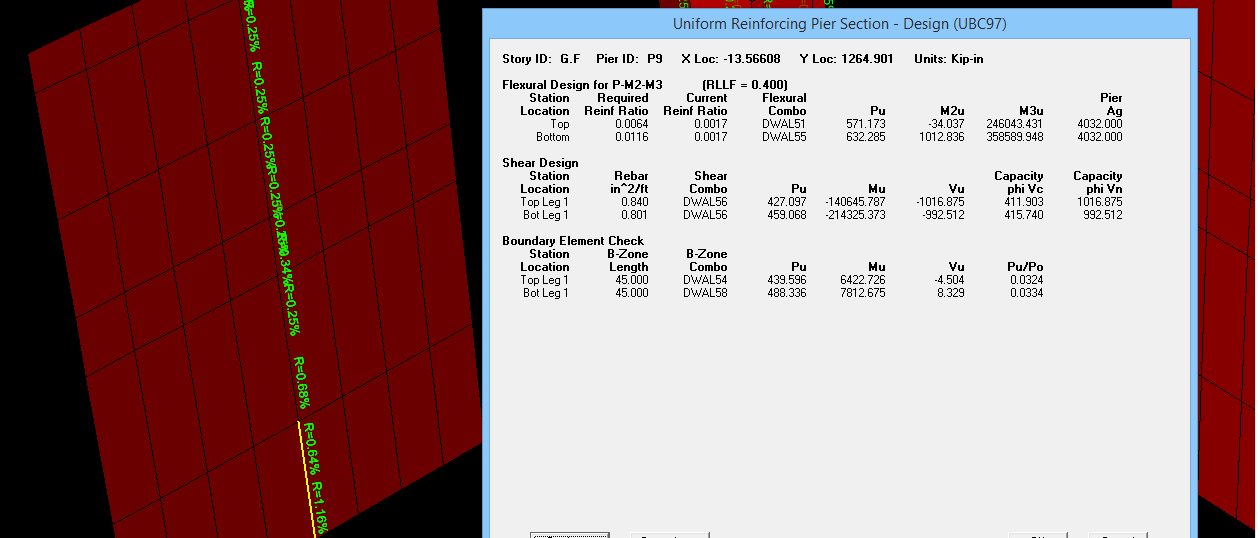
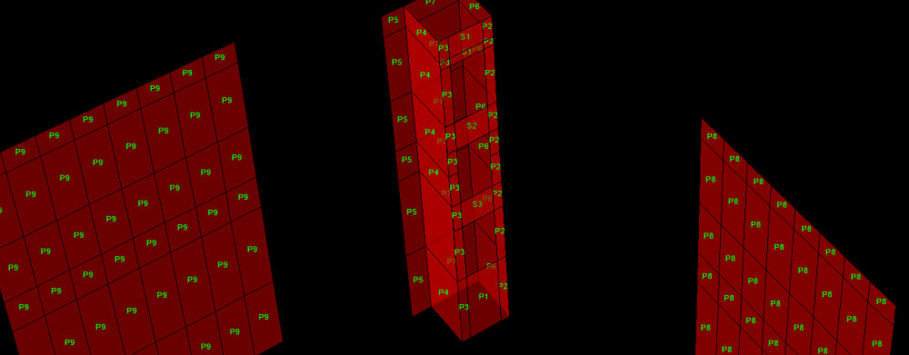
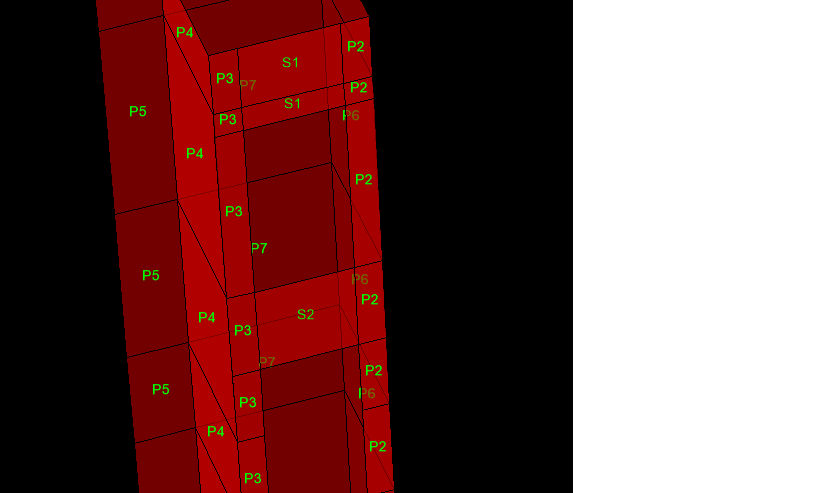
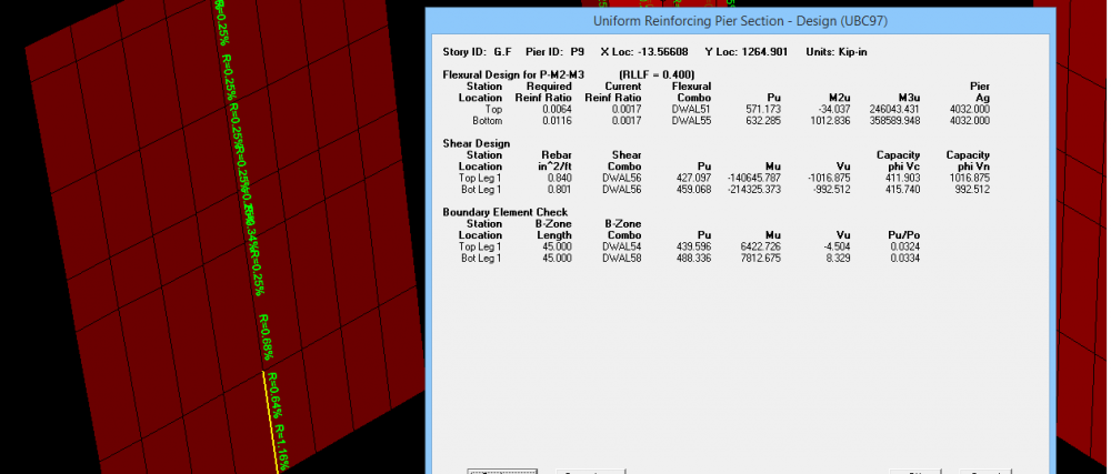
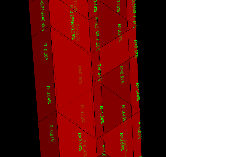
Last month, i design a structure with shear walls. I will attach more documents. What i know/remember i will share with you. In simple, Pier is similar to column and Spandrel is similar to beam. Shear wall is modeled in etabs as shell element. You are to assign it either pier label or spandrel label (Depending on situation of shear wall) to design a shear wall. If you want to design a shear wall, it mostly needs peir label to be assigned. But for the portions of shear wall above openings, as its behavior is somewhat like beam resting on two supports, you need to assign it a spandrel label. I have attached screen shots of my model where you can see i have assigned pier label to the vertical elements and i have assigned spandrel labels to the elements spaning horizontally above openings. The reason behind is detailing based. The detailing in vertical elements of shear wall is similar to wall (or column) and its design is based on considering it as an element resisting majorly AXIAL FORCES + MOMENTS along with inplane shear forces. (Theoratically it acts as a cantilever beam spaning vertically which again represent behavoiur similar to column). I have also attached screen shot of design detail of pier which reports total vertical steel in wall with respect to section area for resisting moments, horizontal steel for resisting shear and some times boundry elemtns (i.e. special detailing at ends of shear wall exactly as in column i.e. shear rings confining vertical bars). I have also attached screen shot of design detail of spanderal which reports top steel, bottom steel, to resist moments similar to beam and vertical steel to resist shear along with DIAGONAL reinforcement some times needed to account for reversal of forces. I will attach more documents throwing detailed light on shear wall design i found few weeks ago. Also my model is attached (it is in seismic zone 4 from where you can get idea about pier labeling and spanderal labeling) One important thing is that, pier label and spanderal label also meant to integrate forces. i.e. if you assign same pier label to all walls in a floor connected with each other, the software will report results only for one and critical wall because all walls were assigned only one pier label. If you want to have multiple outputs at multiple walls, you should assign them different pier label. in image number 5, note that i have not assigned any pier to the selected portion of wall. hence no reporting of results is done. Etabs Center Portion.e2k

-
Waqas Haider reacted to a post in a topic:
Shake table testing for Buckling Resistant Braced frame
-
Assalam o alaikum, There is a job opening for structural draftsman in Kashif Aslam and Associates, Lahore, with minimum of 3 to 4 years of experience in structural drafting. Interested candidates may send their CV at waqas.haider@kaa.com.pk Please forward to the concerned person in your circle also. Thanks.
- 1 reply
-
- 2
-
-
- draftsman job
- strcutural draftsman
- (and 1 more)
-
Torsion: Reinforced Concrete Members
Waqas Haider replied to UmarMakhzumi's topic in Journal/ Articles/ Tutorials
Kindly clarify my confusion in either thread. Thanks. -
Design For Shear And Torsion Using Etabs
Waqas Haider replied to Hasnain Khan's topic in Concrete Design
I am confused regarding this approach of reducing torsional modifier to such great extent. According to ACI 11.5.2.2 In a statically indeterminate structure where reduction of the torsional moment in a member can occur due to redistribution of internal forces upon cracking, the maximum Tu shall be permitted to be reduced to the values given in (a), (b), or (c), as applicable: (a) For nonprestressed members, at the sections described in 11.5.2.4 φ4λ Sqrt(fc ′) A2cp / Pcp It says that we can reduce torsional moment upto a specified limit. Not to zero or 0.001. In its commentary it says, For this condition, illustrated in Fig. R11.5.2.2, the torsional stiffness before cracking corresponds to that of the uncracked section according to St. Venant’s theory. At torsional cracking, however, a large twist occurs under an essentially constant torque, resulting in a large redistribution of forces in the structure.11.34,11.35 The cracking torque under combined shear, flexure, and torsion corresponds to a principal tensile stress somewhat less than the quoted in R11.5.1. When the torsional moment exceeds the cracking torque, a maximum factored torsional moment equal to the cracking torque may be assumed to occur at the critical sections near the faces of the supports. This limit has been established to control the width of torsional cracks. Also according to Nislon, this distribution is only possible after extensive cracking as highlighted in below pic. So I doubt the approach used to neglect torsion upto 0.001 level What i got from the 2nd attachement of Zain Saeed the author is dividing Tcr with Tu to find how much reduction in Tu is needed to reduce torsion upto Tcr which is, as mentioned above, is necessary to keep torsional crack widths in control. and hence using the modifier for each section defined for beam. It might be a bit lengthy task to evaluate for each type of section ( most loaded members of a type of beam may be checked only), but the approach seems more realistic. Kindly comment as I think if even we reduce to 0.001, still this redistribution in torsion is not possible without large twisting which is not possible without excessive cracking. So reucing upto such a low value does not seem good.