asadishaq
-
Posts
74 -
Joined
-
Last visited
-
Days Won
9
Content Type
Profiles
Forums
Events
Everything posted by asadishaq
-
@Hussam Afifyyou can manually apply the overturning check, multiply horizontal load (either from wind or seismic) with the distance from the bottom of the footing to get your overturning moment, and then check against the stabilizing moment i.e (weight of the structure + soil above footing multiplied with their respective lever arms.
- 4 replies
-
- 1
-

-
- sliding
- overturning
- (and 1 more)
-

Etabs model dont show auto seismic calculation in summary report
asadishaq replied to kHURRAM ALI's topic in Software Issues
WALEKUM SALAM! Dear Khurram, After running the model go to file menu >Print tables > Input menu and select load options and select all load cases then print the summary, it will show the automatic lateral load calculations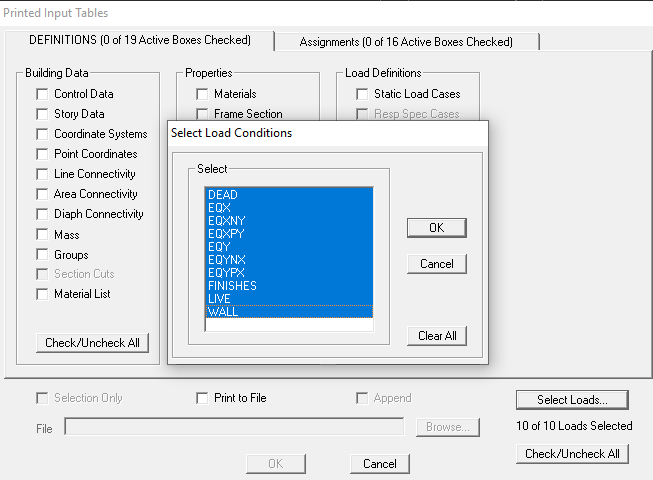
-
Based on Technical Report No. 65, Expansion Joints in Buildings: issued by Building Research Advisory Board, Division of Engineering, National Research Council, USA. As per Figure 1 in the above referenced publication, the maximum allowable building length without use of expansion joints, for design temperature change greater than 70º F (39º C) will be 0.85x350=297.5 ft = 90m. In view of above, we would like to avoid expansion joints in any building which is less than 90m in length, except where a seismic joint is required due to configuration of the building (plan irregularities, re‐entrant corners, etc.) or due to different lateral force‐resisting systems for the two parts of the building.
-
What is the criteria for providing hanger bars? any code reference etc.?
-
Shrinkage strips are temporary joints that are left open for a certain time during construction to allow the shrinkage to take place without inducing stresses. It is usually 2 to 3 feet wide across the entire building and should be cast 2 to 4 weeks later than the adjacent portions.
-
Follow the link below, I hope this will clarify your query. https://wiki.csiamerica.com/display/etabs/ETABS+v7%2C+v8%2C+and+v9+Translator
-
If the frame is located in zone 3 or 4 it should be SMRF, and if it is in zone 2 it should be IMRF.
- 11 replies
-
- 1
-
-
- structural systems
- ubc 97
- (and 1 more)
-
EA consulting is very good organization, they have good projects and have very experienced professionals, working environment is also good they have bridge department and also the building department.On the other hand M&B is equally good as EA they only have Building experts and they are now a days doing very good high rise projects.
-
Beams and Columns Over-stressed Next to Shearwall
asadishaq replied to asadishaq's topic in Software Issues
Dear Umar Bhai, These are the concrete columns,I want to know how should I detail these columns if I provide the hinges in ETABS at top and bottom of the columns. -
Dear All Experts, Can we provide hinges in the columns at top and bottom? I am asking this question in a scenario that my columns are very close to shear walls and are getting very high moments.
-
https://www.csiamerica.com/products/safe/watch-and-learn watch the tutorial for SAFE foundations uplift
-
Dear All While visiting the site I observed water dipping out from these cracks on the slab soffits,please see the attachment. What type of cracks are these, and are they alarming for us. Type of slabs are two way slabs supported on beams,slab thickness is 8 inches and span is 27 feet by 31 feet. In my understanding these are yield line cracks because they are resembling the yield line patterns. slabcracks.zip
-
Providing 12" PCC cannot controll the settelments because on the application of load this PCC layer will be crushed and will change in to a powder form.
- 2 replies
-
- 1
-
-
- Fill
- loose soil
- (and 1 more)
-
wasalam, Dear Waqar, For allowable deflections of two way slbas please refer to the table 9.5( of ACI 318-08,where you can find the maximum permissble deflections for two way slabs.secondly if you want the procedure how to check, it can be easily done by importing your floor in SAFE where you can check the deflection of slab at any point. Thanks
- 2 replies
-
- 1
-
-
- two way slab
- allowable deflection
- (and 1 more)
-
inter story drift is exceeding in basement levels,also torsional irregularity greatly exists at different levels.should we consider the underground stories for seismic drift and torsion???
-
following load combinations are used in the model.design preferences are ACI 318-02,Building is in zone three with SMRF system for lateral loads.and there is an inactive fault near the building just 500 meters away from the site,a special geological study has been conducted which shows zone 2B but the vetting consultant asked the designer to design it for zone 3.load combinations are as follows. 1.4D 1.2D + 1.6L 1.2D +1.0L + 1.6WX 1.2D +1.0L - 1.6WX 1.2D +1.0L + 1.6WY 1.2D +1.0L - 1.6WY 1.2D + 0.8WX 1.2D - 0.8WX 1.2D + 0.8WY 1.2D - 0.8WY 0.9D + 1.6WX 0.9D - 1.6WX 0.9D + 1.6WY 0.9D - 1.6WY 1.2D + 1.0 EQX 1.2D - 1.0EQX 1.2D + 1.0EQY 1.2D - 1.0EQY 0.7D + 1.0EQX 0.7D - 1.0EQX 0.7D + 1.0EQY dynamic analysis is performed using eigen vector.
-
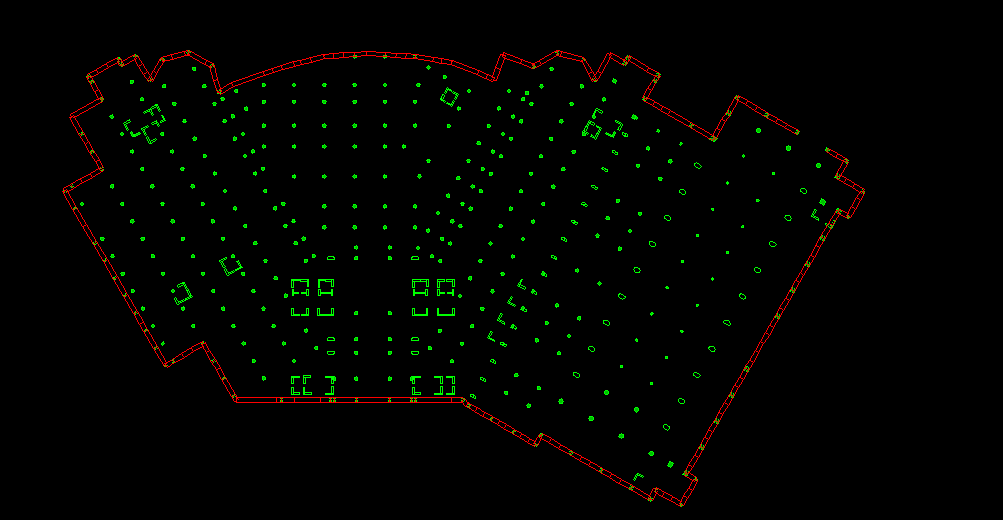
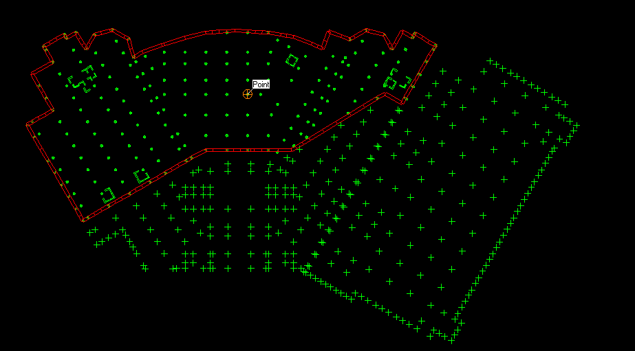
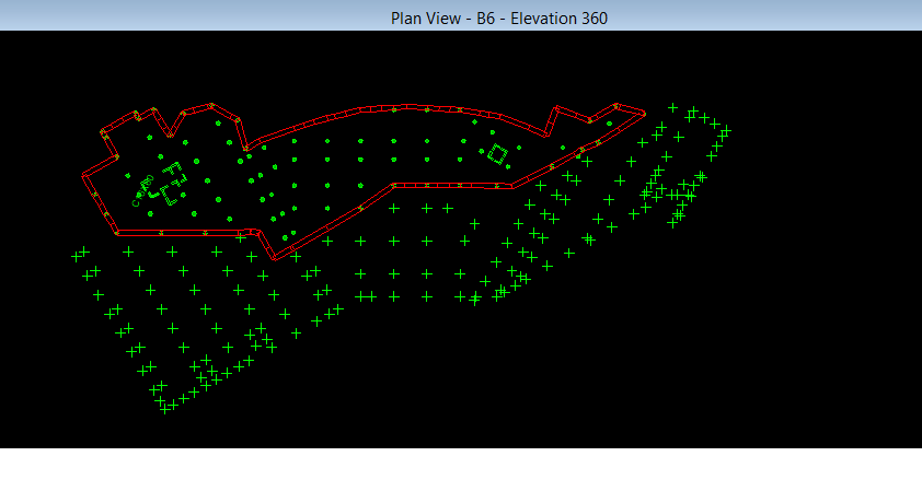
The building is located on hilly area near murre and it has 8 basements and 10 upper stories 4 basements are totally confined from all sides,after B4 level it is confined from 3 sides.foot print of the building is such that B8 footprint is very small than B7 and step by step it is increasing till B4 and after B4 rest of the basements are same.I am attaching the sections of building also,the designer choose the B4 level to the lower story for seismic force.when i am checking my base shear at B4 level only 54% of base shear is taken by columns...since there is no special consideration been made by the designer to design the retaining walls for seismic forces,retaining walls are designed as a normal walls.the modifiers assigned to retaining walls are 0.7 for bending only the membrane modifiers are 1.the thickness of the whole retaining wall is 4 feet.I am from client side and checking the model kindly give me you valuable comments about this project. A-301-MAIN BUILDING & BALLROOM SECTION-Model.pdf


-
Retaining walls in ETABS absorb much of base shear if our whole basement is confined by retaining walls,what is the correct way of modelling retaining walls? can we neglect them in the model?or if we model them what are the correct modifiers for them, I am vetting a project in which the designer put all the modifiers to 0.7 in membrane and bending and retaining walls is absorbing 54%of base shear in X direction and 46% in Y direction is this the correct way of modelling???
-
Links are still not opening
-
I have a concrete IMRF system with shear walls are also present,what will be the value for ct?is it 0.02 or 0.03?
-
Ct=0.035 for steel moment resisting frames Ct=0.030 for reinforced concrete moment resisting frames and eccentrically braced frames Ct=0.020 for all other buildings My question is that the value of ct is dependant on material property like steel structures or concrete strucutures or wooden structures or it depends on the type of frame system like dual frame system IMRF SMRF ?
-
I have been searching the example in MacGregor but didnt find it....
-
Assalam o alekum Providing bracings in the building greatly reduces lateral diaplacements can we provide concrete bracings? or what property we should assign to brace element a beam or a column?,I modelled a concrete brace element in ETABS but Etabs donot design it for axial compression or tension
- 3 replies
-
- 1
-
-
- concrete braced frame
- etabs concrete brace
- (and 1 more)
-
Effect Of Temperature Changes On Buildings
asadishaq replied to asadishaq's topic in Concrete Design
I have modelled a building on ETABS and applied a Temprature Gradient of 54 degree farehnhite only on Roof becuase in my opinion only roof will be exposed so temperature loading is applied only on roof and the exposed elements of the building. Am i doing right kindly guide me i have never done this before. -
Kindly Guide me how to do temprature analysis of buildings on ETABS