

Ayesha
-
Posts
578 -
Joined
-
Last visited
-
Days Won
138
Content Type
Profiles
Forums
Events
Everything posted by Ayesha
-
Also, see this:
-
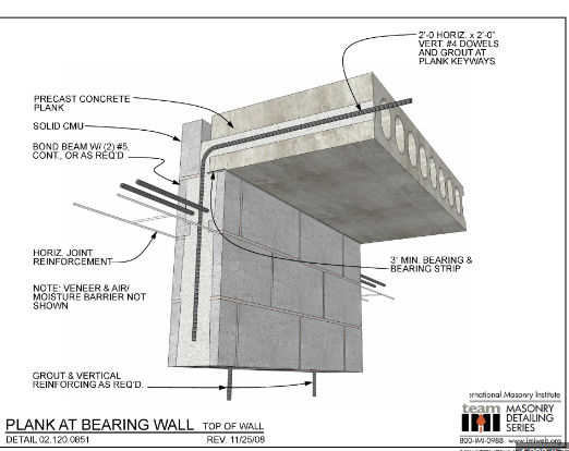
Normally the connection between brick wall and slab will need to be detailed. It can be a shear connection with an angle transferring shear from slab to brick wall and you can model this arrangement as pinned or your can provide rebar. See attached.
-
The building framing is complex. If L2 is basements, irregularities need to be calculated for level above basement. If you keep the framing as is, from L2 to L8 should be single story, for global structure check and for each individual tower I would do local check between each story as well. This is based on my engineering judgement. I don't have any references detailing this.
-

Meshing of Frame Elements Option in ETABS
Ayesha replied to Zeeshan Ahmad's topic in Software Issues
Normally there isn't a hard requirement to mesh frame elements if they are not supporting area elements. I believe there is a setting on number of internal sections that matters more for frame sections as it reports the number of points along length were results are calculated. You can always look at deformed shape to see if there is something wrong with the model. -
The building is really irregular. I would suggest isolating different sections of building if it is possible considering building envelope and architectural plans. For concrete buildings, the normal rule of thumb that I have seen out of handbooks in 180 feet. You can also refer to ACI 224.3R to further details. Hope that helps.
-
In my opinion the section applies to all type of buildings. You can read ASCE and see applicability from there as well.
-
I think you forgot to attach the report or provide a link for it.
-
what is your question?
-
SAFE V16-Analysis but no results after exporting floor file from ETABS
Ayesha replied to Kel's topic in Software Issues
There could be number of reasons for this. The first step in my opinion will be to ensure if the file from ETABS has been correctly exported to SAFE. Please follow the following link and ensure that step is done correctly and try again. https://wiki.csiamerica.com/display/safe/Import+ETABS+into+SAFE+FAQ -
There is some additional information on Mass Irregularity in Appendix F and Strong Column/ Weak Beam discussing in Appendix G of the document.
-
Welcome to the forum. You have an interesting background. Sure, if you can provide details and plans then other people can provide some suggestions.
-
Point spring I assume you are referring to single spring. Single spring represents single pile.
-
i am not sure if there is an option in ETABS to do it. I would suggest to export reactions to excel and check the reactions against max tensile and compressive capacity of pile.
-
This is an interesting situation. I also agree with @Ebeid that releasing beams wouldn't be a wise thing to do as it will also effect lateral force resisting system. The frist thing that I would suggest would be to sharpen the pencil and see if the loads have any contingency and remove that contingency from loads and checking if the provided reinforcement in the column works. If that doesn't work, you can add more columns per bay to make things work but it would require new foundations.
-
Concrete compressive strength evaluation of bored piles
Ayesha replied to abbaskhan2294's topic in General Discussion
There are different way depending upon the risk category of the structure. Pile capacity of concrete is one things and geotechnical capacity is another. The best way would be to do a pile load test on this pile group. Geotechnical consultants normally do such test and it helps verify capacity of existing piles both structurally and geotechnically. For concrete strength, like you said core testing is one way. I am not familiar with GPR for strength testing of concrete piles. I have seen a lot of results of GPR surverys to find buried lines but nothing to determine strength. Hope this helps. -
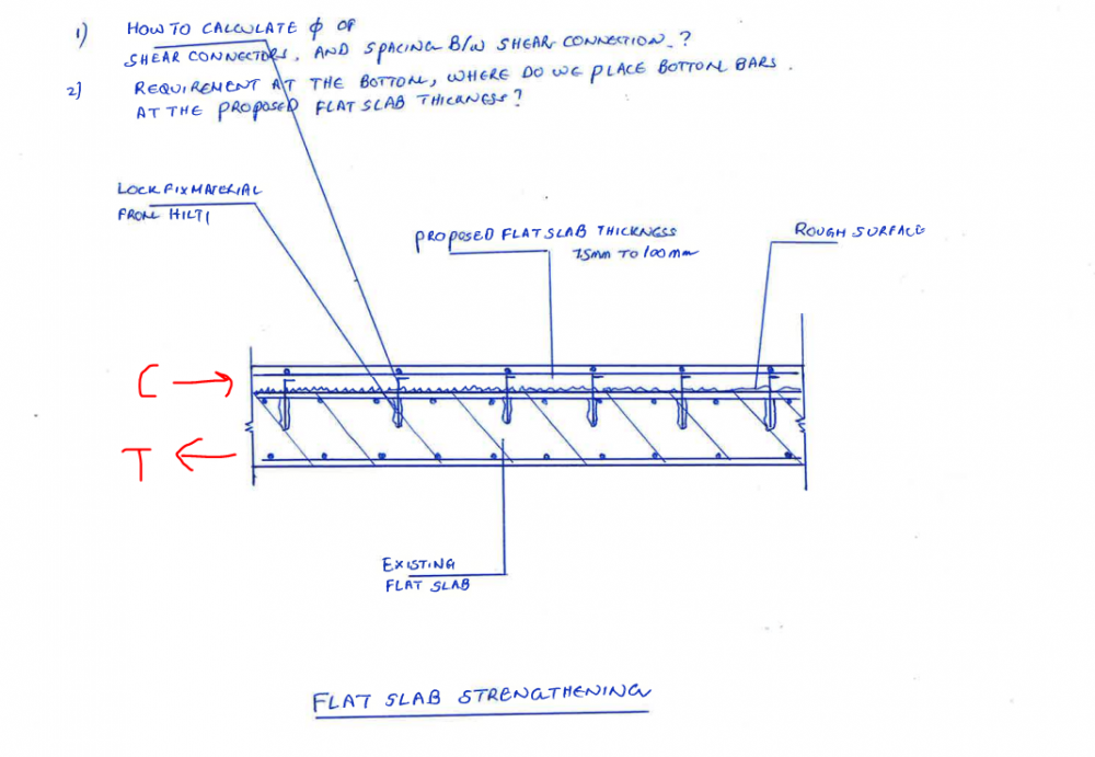
I haven't done any slab retrofits myself, but looking at the picture, the following solution comes to my mind. You can consider the additional thickness of slab + original one as one slab. Do your analysis and find the compressive and tension force in a unit width and design the studs for that width. That force will tell you how many studs you need. Also you need to check stud capacity and Hilti adhesive capacity. Stud capacity should be easy as it is made of steel. For Hilti, yo can use their software Profis.

-
retrofitting Inserting a new column in existing RCC frame Building.
Ayesha replied to Sajid Usmani's topic in General Discussion
Thanks for your post. What is your question? -
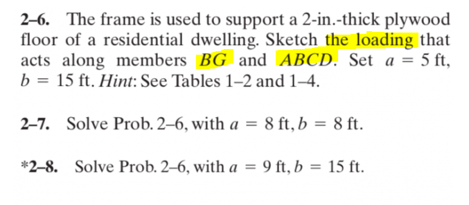
It is not shown because the question requires the person to calculate "Loading" for "BG" and along "ABCD". That is what the solution is provided for.
-
Please check your analysis log. If there is an error that is preventing the deflected shape, it would be pointed out there.
-
Is this a construction problem like is the column erected out of plumb? You can check a titled column in your software and see if it still passes with P-Delta. Other items you can do is change the framing add new columns to reduce load on that column.
-
AH and DE are load bearing walls that is why. The question is about the need to draw "loading sketch" so that why reactions don't matter.
-
You can check this thread on modelling masonry in SAP2000. I am very sure that one of the documents in the thread explains how to do it. Another one is this thread:
-
Beams are not composite. Slabs are composite if there is metal decking with concrete.
-
I don't have any reference but it is not different than any support. Create an analysis model, apply wind loads based on area of the barrier and on the supporting members, get your foundation forces and design anchor bolts and foundations accordingly.
-
I think what he said is the only option. Any mode can be higher than other modes based on structural configuration. You should look at the deflected shape of the mode to see if it makes sense.


