Leaderboard
Popular Content
Showing content with the highest reputation on 03/08/17 in all areas
-

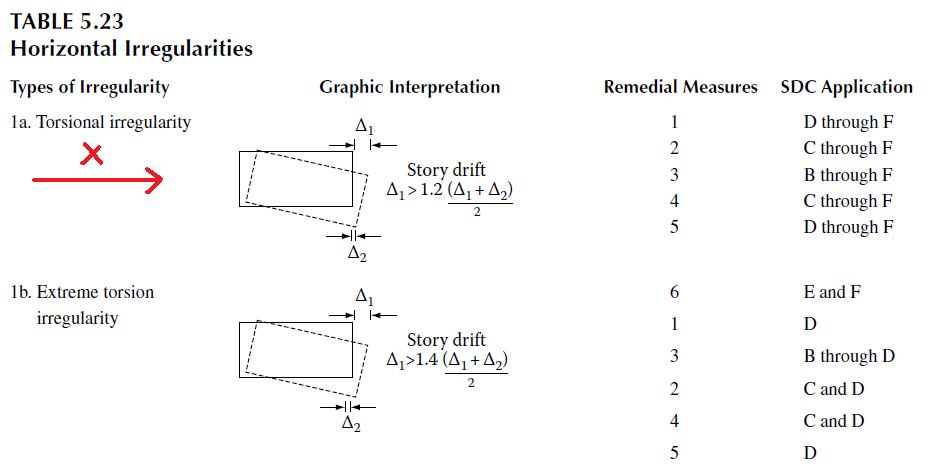
Torsional Irregularity according to UBC97
UmarMakhzumi and one other reacted to WR1 for a topic
Yes you are right. If loading direction is X, check x displacements on point 1 and 2 on the edge that is perpendicular to loading direction. Following will clarify; 1. Load in Y Direction Source: FEMA; https://c.ymcdn.com/sites/www.nibs.org/resource/resmgr/BSSC/Topic09-SeismicLoadAnalysis.pdf and 2. Load in X direction: Source: Reinforced Concrete Design by Tranath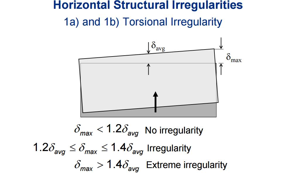
 2 points
 -

Shear wall location
UmarMakhzumi and one other reacted to Suarez for a topic
Divide the structure into blocks with regular shape (like center portion with open yard being a block separate by joint). The multipurpose hall (only this has basement??? provide more sections) so separate it from rest of building. Then analyze and design it like regular frame structure for zone 4 and steady the results. Only then you can go for Shear Walls.2 points -
Plot of dynamic response vs rise time of load/natural frequency
Suveksa shrestha reacted to WR1 for a topic
1. Your observation is correct that Sin(6.8) on calculator = sin(radians(6.8) provided your calculator is set in degree units. What you have used in Excel formulas [ sin(radians(6.8) ] is correct if; the angle 6.8 originally was in degrees. Was it in degrees? See the formulas you have attached in Excel. I do not think so. Why? Because circular frequency (w) is usually is rad/s. So your units are already in rad and you do not need convert them further and Excel is already set in rad units so just use directly the sin(6.8). This is what @Saad Pervez pointed out.1 point -

Plot of dynamic response vs rise time of load/natural frequency
UmarMakhzumi reacted to Saad Pervez for a topic
In Excel, default unit for trigonometric functions is Radians. You're using the formula SIN(RADIANS(VALUE)). You're forcing excel to assume that the value already in radians is in degrees. SIN(6.28 radians) should be zero, using your formula the value is 0.11. Remove the RADIANS(), use SIN(VALUE) instead.1 point -
Shear wall location
UmarMakhzumi reacted to WR1 for a topic
1. You need to divide the buildings to avoid irregularities especially in zone 4. 2. start with a crude model, no shear wall (only columns) and try to get the general feel of the structure. For that you could also roughly estimate the gravity loads (for mass source). For example 15-20 kpa let say (including sw+sdl+ll) as gravity load. 3. Iterate by putting in shear walls where you need it. Once the crude geometry is finalized you can go for detailed modelling/design and you will find out the importance of concept stage design at early stage.1 point -

Building Drifts In Etabs
JL07 reacted to UmarMakhzumi for a topic
"Ever since strength-level (as opposed to service-level) design earthquake forces were introduced in the 1997 Uniform Building Code (UBC), as indicated by a load factor of 1.0 on E in strength design load combinations, it has been required that drift computations be done directly under those strength-level forces. The drift limits were adjusted accordingly. You never reduce the strength-level design earthquake forces to service-level forces for the purposes of drift computation. This is true of the 1997 UBC, all editions of the IBC, and all editions of ASCE 7 since 1993." My original post is referring to use strength level load combos in the light of justification provided. In addition to that, using dead and live loads with earthquake is a good idea as they cover any lateral deflection due to gravity load (mostly observed in non-symmetric frames) which wouldn't be accounted if only earthquake load case is used. Thanks.1 point -
Building Drifts In Etabs
Waqas Haider reacted to WR1 for a topic
Inter-story drift limitation is intended to limit the damage. Abs disp of max point of upper stories wrt to base is to check for seismic separation. Both checks are must.1 point -
Building Drifts In Etabs
JL07 reacted to UmarMakhzumi for a topic
Good article; I will throw my two cents. Seismic drift values are much larger than wind values. UBC uses maximum inelastic response displacements rather than the design level displacements to verify the performance of the building. As stated above, the seismic drift limits are 2% & 2.5% of the story height for long and short -period buildings. So, for a floor to floor height of 12 feet the max. allowable inelastic drift value would be 2% of 12 feet= 0.02*12*12inches=2.88 inches. For wind for a 12 story height, drift would be L/400=12*12/400 =0.36 inches, A comparison of both wind and seismic drift limits shows that earthquake inelastic displacements are quiet large compared to wind displacements. That is why proper detailing is emphasied in seismic design. Moreover, when calculating ΔS for seismic, make sure: you have included accidental torsion in your analysis. use strength design load combinations: 1.2D + 1.0E + 0.5L & 0.9D + 1.0E You are using cracked section properties for reinforced concrete buildings. Typical values are Icr walls= 0.5EcIg, Beams = 0.5EcI g & for Columns 0.5 - 0.7 EcIg.1 point