

Suarez
-
Posts
30 -
Joined
-
Last visited
-
Days Won
3
Content Type
Profiles
Forums
Events
Everything posted by Suarez
-
What is a negative torsional shear? Where has it come from, and how is it accounted for in the design?
-
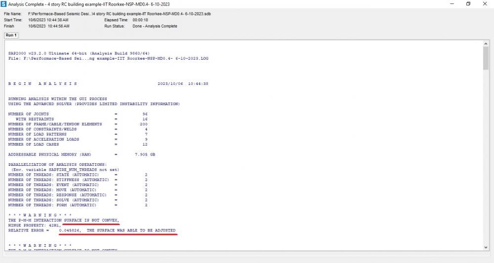
The following error is being shown after running pushover analysis of 4-story RC building in SAP2000. "The PMM interaction surface is not convex. Hinge property: 42H1, Relative error = 0.017389. The surface was able to be adjusted." I have tried to change monitored displacement and other options but in vain. What is the reason for this and what could be the remedy?
-
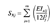
The building that I am designing is multi-storey MRF building. I want to compare story stiffnesses using ETABS and a following formula, The results between the two are very different. Why is it so? What other method is better?
-
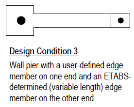
I was referring to this condition.
-
What if a boundary element of a shear wall, being part of a dual system (reinforced concrete), is overstressed while using ETABS? (what if boundary element would be poured separately, during the construction stage). Question is, what is the reason for overstress? Secondly, by pouring the boundary element separately from the shear wall, can it still be called boundary element OR it would be considered as a separate column, part of moment-resisting frame? PS. Reinforcement detailing (as per ACI code) is just like boundary element, during design as well as construction stage.
-
-
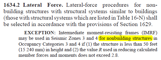
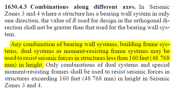
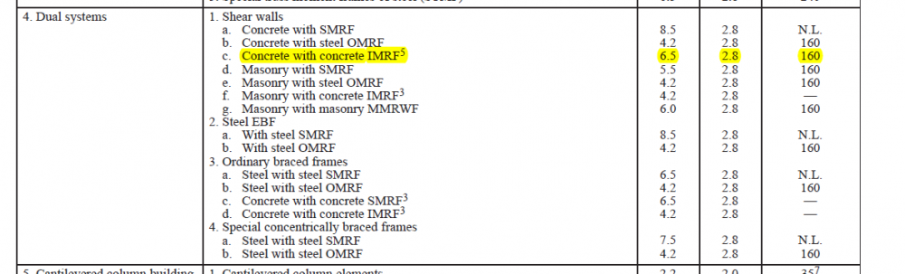
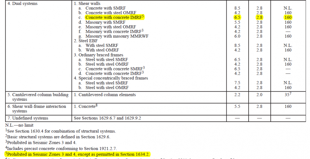
The following statements seem to be contradictory i.e., UBC 1630.4.3 and TABLE 16-N, 4.1.c is prohibited in Seismic Zone 3 and 4. Can dual system with IMRF be used in residential building structure in seismic zone 3 or 4 with height less than 160 feet?
-
I think (I may be wrong!) masonry walls should be analyzed as "Strut & Tie Model" not as a shell element.
-
1. Sections used earlier: Channel 6"x 3" for top & bottom chord. Later changed to double-channel 6" x 3" back to back. 2x2x1/4 angle for bracing. Later changed to double-angle 2x2x1/4 back to back. Changed further to bigger sections...... In steel design sheet it says ..... Warning l/r > 60, Check bracing at beam-column connections.
-
During the seismic design of this truss, following errors are displayed: vertical Sections are seismically non-compact. (I changed to bigger sections but still in vain.) l/r > 60, Check bracing at beam-column connections. (Columns are braced at mid height but still in vain.) I would appreciate any thought on the subject.
-
The attachement is an steel truss access bridge on a earthen dam. What I want to ask is following: What should be the max. allowable vertical displacement in this case? How can I design the connections in SAP2000? Please say whatever you feel like....... constructive criticism. I'm all ears. New Picture (1).bmp New Picture (2).bmp
-
AOA. Can anyone please tell me the rates for preparing a fabrication / shop drawing? I have search on the internet and came to know of 0.5% - 1% of the cost, but I'm not sure about it.
-
Autodesk Revit is for one. Other is Tekla structures.
-
I think one do not need a PhD to differentiate right from wrong, if he ask himself. The minimal should be "Does my action causes danger to the life of any human being?" Rest paves out as we go from time to time, and from moment to moment. But then there are engineer who act against another engineer, or he's not ready to help a fellow engineer. That's a problem specially in Pakistani engineers. Like Pakistani architects use AutoCad (Cracked) and he does not impose himself on another Architect, by saying "Go! and buy a licensed AutoCad!!!!!!". They just work and help another architect. Sadly, you can not say this for engineers. Same goes for PEC..... Architects register with PCATP once. They do not register again if they want to be a consultant and pay in thousands. Similarly, they do not pay again and again if they want to be a contractor/constructor. ....... Engineer Engineer Ka Dushman Hai !!!!!!!!! (Buhut maazrat K sath)
- 2 replies
-
- 1
-

-
- structural design
- design responsibility
- (and 2 more)
-
Divide the structure into blocks with regular shape (like center portion with open yard being a block separate by joint). The multipurpose hall (only this has basement??? provide more sections) so separate it from rest of building. Then analyze and design it like regular frame structure for zone 4 and steady the results. Only then you can go for Shear Walls.
-
Dear members, I am using ETABS v9.7.4 and i want to use the newer versions for detailing purposes. I am trying to install ETABS 2013 or 2015 (cracked version), but its not cracking / working. I followed every steps as directed but Can't open. Help plz.
-
Pile Design For Machine Foundation
Suarez replied to Mohammad Yaseen Yousafzai's topic in Foundation Design
Dear Umar, You have no idea how important & informative your replies has been. I have learned so much from these posts and they have been so forthcoming. I really appreciate and admire, and I really recognize and acknowledge your efforts. Following replies are in good faith and utmost respect: 1. Time History Function & Load Case: You have applied the loads but you have to associate............... I had already done that [New Picture (4) & (5)]..... 2. COM Location: You should not assume and ask vendor to provide you........... I shall ask vendor for CoM locations. "Load Points" are load locations on top of deck for static loads & dynamic loads (unbalanced forces) which were provided by vendor with machine drawings along with machine dimensions etc. These locations are Foundation-Bolts-Locations which connects machine to foundation through base plate. 3. Results: Before you proceed, ask your vendor, what is the location where the amplitude needs to be satisfied. Is it the COM locations? Is it the Top of Concrete Table Top? In my last post, I mentioned what vendor had ask for, "Maximum permissible amplitude of vibration on top of deck is 30 microns." Attached is "Display Plot Function Traces" ..... [New Picture (6)]. Thx a bunch. New Picture (4).bmp New Picture (5).bmp New Picture (6).bmp -
Pile Design For Machine Foundation
Suarez replied to Mohammad Yaseen Yousafzai's topic in Foundation Design
Loads are applied at TOP DECK-points (TTF-zip-file attached in my earlier posts) provided by vendor with static loads (vertical direction only) & dynamic loads (Unbalanced forces in x,y & z directions) for respective machines. Top deck has common bottom level with different thicknesses. Left side of the deck is for TURBINE (different color in SAP2000 picture) & right side is for Alternator (TTF-zip-file attached in my earlier posts). Maximum permissible amplitude of vibration on top of deck is 30 microns (Provided by Vendor). Lines from tutorial - "In many cases, the vendor will give separate CoM locations for major components (pump, gearbox, turbine, turbine rotor, generator, etc.), in which case you would add joints for each component of the equipment where you will assign force/weight which will be converted to mass." I'm assuming that LOAD POINTS provided by vendor are aforementioned CoM-locations. In that case, I have applied static & dynamic loads at these locations and have run TIME-HISTORY FUNCTION, which yielded into results posted earlier. -
Pile Design For Machine Foundation
Suarez replied to Mohammad Yaseen Yousafzai's topic in Foundation Design
Please have a look again. All three parameters are there in the spreadsheet, i.e., displacement, velocity & acc. -
Check out this tutorial. ETABS-Example-RC Building Seismic Load _Time History_.pdf
- 2 replies
-
- 1
-
-
- response spectrum
- seismic tall building
- (and 1 more)
-
Pile Design For Machine Foundation
Suarez replied to Mohammad Yaseen Yousafzai's topic in Foundation Design
Attached are vibration parameters. I appreciate your time & input. Book2.xls -
Pile Design For Machine Foundation
Suarez replied to Mohammad Yaseen Yousafzai's topic in Foundation Design
After the application of Time History Function as per CSI-tutorial "Vibrating machinery steel skid on piles", the undesirable range of frequencies (20% above and below of machine operating speed): Turbine - mode 11 to mode 16, Alternator - mode 35 to mode 47. The result of frequencies are almost the same as before. Please comment. Book1.xls -
Pile Design For Machine Foundation
Suarez replied to Mohammad Yaseen Yousafzai's topic in Foundation Design
Attached is zip file containing info of loads and model picture. I do not have "Time-history Function Data" of my project. Thank you anyways for the input. TTF.zip -
Pile Design For Machine Foundation
Suarez replied to Mohammad Yaseen Yousafzai's topic in Foundation Design
Do u ve manual (or can u refer to a manual or book) for this procedure? Also, I have designed mat foundation (not piles) for this table-top. Please elaborate this point "Then run Modal Time History Function by equating your forcing function to the frequency of the mode(that's how you check resonance)". Attached is modal analysis result for frequencies of Turbine & generator. I am confused as to what should I do with analysis. Should I apply turbine loads & generator loads separately in two SAP2000 files? Or as I have done here by combining both in same single file? I would appreciate any and all kinds of inputs. Tabletop foundation - Modal Analysis Result.pdf -
Pile Design For Machine Foundation
Suarez replied to Mohammad Yaseen Yousafzai's topic in Foundation Design
Dear Umar Bhai, Modal analysis of a Table-top foundation has been done on SAP2000, with following result: Frequency of foundation in mode-12 (last mode) = 25.72 Cyc/sec. (Mode-12 has maximum frequency value) Turbine's Frequency = 117 Cyc/sec. Generator's Frequency = 25 Cyc/sec. Plz comments


