EngrUzair
-
Posts
476 -
Joined
-
Last visited
-
Days Won
242
Content Type
Profiles
Forums
Events
Everything posted by EngrUzair
-
CSI SAFE also has a Detailer. You may export ETABS results to SAFE and using the commands available under its 'Detailing' menu option, it will prepare structural drawings for you. You may give it a try to see whether it fulfills your requirements or not. Regards.
- 3 replies
-
- 2
-

-
- structural drawing
- software
- (and 2 more)
-
it would depend upon the material of construction being used. In general, load combinations involving seismic (earthquake) effects will be critical for RC structures. Whereas, for steel structures, those involving wind effects will be more critical. In practice however we check the structures for structural safety against the load combinations (specified by applicable material design / loading codes) involving all type of loads that are expected to be resisted by the structure during its entire design life. Regards.
- 13 replies
-
- 1
-
-
- combinations
- load
- (and 2 more)
-
Agreed, in general. However, there are situations where provision of an RC beam and even RC wall becomes necessary. My previous reply was with reference to the general case of two wall footings of same slab size (both in plan and in thickness), but one of them with an RC beam of height more than the thickness of footing slab. In practice however the type of footing used will vary with the site situation. For example, in case of an ordinary two storey masonry wall building without basement, simple strip footing (of a uniform thickness) should be ok in most of the strong soils with uniform strata. On the other hand, strip (or even a raft) footing with beam(s) may however be required to avoid differential settlement for sites with scattered loose subsoil pockets. However, for the specific cases of buildings with a basement, either in weak soils or at locations where the subsoil water level is high, provision of even an external RC wall (for the purpose of retaining earth, or prevention of moisture inside the building etc.) becomes desirable. The problem highlighted in the Original Post also falls in this latter category. Regards.
-
A wall footing with an RC beam (of height greater than the thickness of footing slab) will have a greater stiffness than the one without beam. As such, it will have more capacity to resist longitudinal bending of wall / footing caused by any concentrated loads, as well as in spanning over some loose pockets existing within the soil beneath. Regards.
-

KPK Seismic Field Practicing Manual (Urdu)
EngrUzair replied to EngrJunaid's topic in Journal/ Articles/ Tutorials
Very vital information, and in urdu as well for understanding of all. Must be shared with as many construction related people as we can. Thanks @Junaid! for sharing such an important document. Well done! -
Inbox Communication
EngrUzair replied to UmarMakhzumi's topic in Website Announcements/ Problems/ Login/ Registration Issues
Very important message! I myself have received questions in my inbox more than once, from some of the forum members asking for help on various technical matters. However, I have always advised them to put the questions on the forum, as it has multiple advantages, both for the originator as well as for rest of the forum members. By posting the question on the forum (instead of sending to an inbox), the problem is visible to all the members, and it is likely to get not only a quicker response but more & better responses as well. In addition, the question and responses are helpful for rest of the forum members in general, and those members particularly who do have same problems but somehow (due to shyness etc) couldn't ask the same questions on the forum themselves. In view of the above discussion, I strongly second the opinion of UmarMakhzumi, for posting of problems to the forum itself, instead of sending them to inboxes of moderators or other forum members. Regards. -
What are the various spans, slab thicknesses, and beam & column sizes used in the model?
-
You haven't provided any details regarding your structure, e.g., geometry, spans, no. of stories, building usage, seismic zone, etabs version being used, etc. etc. As such, it is difficult to give more suggestions. If you could attach your model file here, people here might help you in a better way.
-
Wa alaikum assalam, 1. Lateral force resisting system (LFRS) is selected primarily based on the seismic zoning (or seismic category) of the area in which a building or structure is to constructed. LFRS selection partially depends upon the preferred material of construction (e.g., Reinforced Concrete, Structural steel, etc) as well. 2. if you don't have load bearing walls in your structure to transfer superstructure ( floor and roof ) loads to the foundation, it is NOT a 'load bearing wall system'. 3. A 'moment resisting system' is the one in which beams and columns are used to transfer the superstructure loads to the foundation. The walls provided in this type of structure are commonly termed as 'infill walls' or non-load bearing walls. HTH Regards.
-
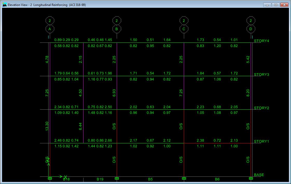
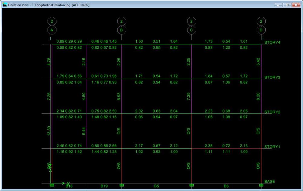
In case you have subdivided the beam (that is supporting the lowest picked-up column) correctly for creating the support point of picked-up column, it is unlikely that you don't get the beam design or reinforcement. It appears that you might have missed something or made some mistake in your model. See the attached image (taken from an ETABS 9 model, I have created to cross-check the results) and note the reinforcement of the left side beam (supporting the picked-up columns), as well as for the supported columns at all levels.
-
There may be several reasons for this. For example, - provided columns are of a larger size, or - there are a number of shear walls, or - you might have erroneously assigned support property to the column joints at all storey levels, instead of those at base level, etc. You should recheck your model carefully to determine, what might be the real reason for the results obtained. Assigning of diaphram is necessary for proper accounting of stiffness of the structure, to resist lateral forces (earthquake etc). Meshing is essential for the transfer of slab load to the edge beams more uniformly. HTH
-
Very good coverage of the event, Waqar! Well done.
-
Umar Bhai! In my opinion, this gathering must take place, even if it turns out to be a meeting of a few members only. Because It will help introduce the forum members to each other as well as to the moderators available at the gathering. For making the arrangement and knowing the anticipated number of participants, you may announce the date, time & venue of the gathering and ask the forum members to confirm their availability for the occasion, at least 24 hours before the gathering time. I am sure, response would be much better this time, compared to the previous one. Moreover, a WhatsApp group may also be created, in order to develop direct communication between the Forum members. Regards.
-
Umar Bhai! Aoa. What is the update on proposed gathering? December is already here. Regards.
-
Two most commonly used standards for the design, construction, maintenance and inspection of water storage tanks, used for fire protection, are National Fire Protection Association (NFPA) standard 22 and and Factory Mutual (FM) standard 4020. While both NFPA 22 and FM 4020 provide nearly similar provisions for the design of water storage tanks used for fire protection purposes, requirements of FM 4020 are of a higher level (more stringent). By 'Seismic zone FM50', your sub-contractor would most probably be referring to the FM seismic zone with a 50-year mean recurring interval for the damaging ground motion. For more details, you may refer to the following link: http://www.pittsburgtank.com/wp-content/uploads/2015/05/FPCmag-FMvs.NFPA_.pdf Regards.
-
AFAIK, provision of additional reinforcement in the slab portion below the wall, will at least reduce the long term deflection to certain extent. Regards.
-
Zebi, Please provide following information regarding degree program and the institution you have attended, to proceed with PEC:- 1. Full Name of the University with mailing address 2. Contact information of the University (web and email address) 3. Duration and Official Start and Completion dates of the degree program attended. Regards.
-
I have talked today with one of my colleagues working in PEC. He is out of city & office for two days. I will In Sha Allah contact him day-after-tomorrow, and will update this forum, hopefully with some positive information, in due course of time. Regards.
-
Yes. How? Go through the following paragraphs. In case of ASD, service loads are used, and both dead and live loads have same load factor of 1. On the other hand, considering the the basic load combination of 1.2 D + 1.6 L, dead load (DL) has a load factor of 1.2 and live load (LL), a load factor of 1.6. Now consider two simple examples. For the first example, assume that a certain beam has to carry a DL of 30 kips, and a LL of 10 kips. For this beam, total design service load for ASD method will be DL+LL=30+10 = 40 kip. For the Strength Design, basic design load will be 1.2 DL+1.6LL = 1.2(30)+1.6(10) = 52 kips. Strength Design load in this case is (52-40)/40*100 = 30% larger than the Design Load for ASD. Now, for the second example, assume that there is another beam, similar to that in the first example, except that the DL & LL values are reverse of those in first example i.,e., now DL = 10 kips, & LL = 30 kips. Total Design Load for ASD method is now DL+LL=10+30 = 40 kip (same as in first example). However, design load for Strength design changes and it is now 1.2 (10)+1.6(30) =60 kips, which is (60-40)/40*100 = 50 % larger. Thus, it is very clear that for both the examples, Design load is the same when using ASD method, and resultantly the member size & reinforcement will also be the same. However, since Design load for Strength Design method is larger in second example (when LL is larger than DL), a comparatively larger member size or reinforcement will be required. Thus, ASD method is generally economical (as compared to Strength Design method) when the live load on a member is larger than the dead load. Regards.
-
You may download soft copy of latest version of AISC structural steel related Design Examples, from the following link for free: https://www.aisc.org/WorkArea/showcontent.aspx?id=33520 This might be helpful.
-
groszni, Articles 18.6 in 'Structural Steel Design, 5th edition, by McCormac & Csernak, 2012', dealing with design of various type of stiffeners might be helpful for you. It contains illustrative examples as well. Regards.
-
Picked-up columns are supported on beams at their lowest point. In order to draw a picked-up column, you will need to create point objects at required location on the relevant beams, and connect the two points (one located on the lower level beam and the second on the next upper level beam) with a line element (defined as a column member). Application of loads, and analysis & design is similar to the other normal columns of a frame structure. HTH
-
I would add the following points, to what Rana has said. 1. Software added Default load combinations for concrete design are denoted as DCON1, DCON2,..., etc. in ETABS. These combinations are initially non-editable. However, these can be made editable by selecting (putting a Tick or Cross in) the Last option ('Convert to User Combinations (Editable)'), simultaneous with selection of design type (Concrete Frame Design, Steel Frame Design etc) check boxes. In the later case, the design load combinations are named as UDCON1, UDCON2,.. etc, by the software, and these can be amended or edited by the user. 2. Before adding load combinations, it should be ensured that the design code selected under the relevant menu item, is the one that is actually to be used for the structure being modeled. 3. Step-by-step procedure for Defining some various types of loads (or Load Patterns) and adding Default load combinations for Concrete frame design in ETABS 2015 has been explained in the following video tutorial. https://www.youtube.com/watch?v=Jvgt2wBhwGg 4. Other loads and load combinations may be added in a similar manner, after making the default load combinations editable, as explained in para-1above. HTH
-
Highest moment capacity for a given column size can theoretically be obtained in following ways: a. Using a steel reinforcement ratio equal to the maximum permissible steel ratio of the applicable design code b. Replacing the concrete with the highest strength concrete, adoptable in given conditions. Both of of these parameters can be set in ETABS as well as SAP2000. Changing the concrete strength in 'Material Properties' should not be an issue. Similarly, provision of steel reinforcement corresponding to maximum steel ratio may also be made easily by selecting suitable size and number of reinforcing bars, while defining the column sections to be used.
-
Increase in column size or provision of shear walls
EngrUzair replied to Hussain Abid's topic in Seismic Design
WA. If there is no restriction, IMO it would be better to increase column dimensions (preferably width), than to provide shear walls. You may even try to change orientation of the columns with higher reinforcement by 90 degrees to check whether the the present orientation of columns is better (resulting in lower reinforcement percentage) or the new one. You are using rectangular columns. However, you haven't shared structural plan of your building. As such, it is difficult to advise you in more detail regarding column sizing or preferable location of shear walls, if required.