

mhdhamood
-
Posts
157 -
Joined
-
Last visited
Content Type
Profiles
Forums
Events
Posts posted by mhdhamood
-
-
Hi everyone ;
For long term deflection analysis using SAFE program by nonlinear load cases, I know that the program can calculate it for the flat slabs. But I wonder if the program can calculate it for beams.
Best regrads
-
THANKS ALOT WAS SO HELPFUL
-
pleGood day ;
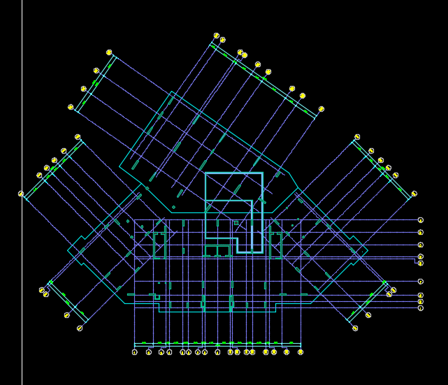
To the expert engineers especially in finite element analysis ; When I have a raft or slab with an irregular shape like the one in the photo attached, I wonder about some points which i need your help:
1. The default local coordinates of the raft/slab are the same as for global coordinates, so when I draw the design strips, shall it be in the same direction of local coordinates or i can draw any design strips in any direction ?
2. If I draw only design strips parallel to the local coordinates theni have to put the steel reinfocement in a way that hard to excute on site since there are areas which have columns in an inclined direction.
3. to solve this issue I think we can draw for some areas the design strips parallel to the local coordinates and for other inclined areas we can draw an inclined design stripps ? Do you agree?
-
hello Engineer Rana ;
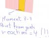
Yes it is taking the moment from one direction .But what i have noticed that the SAFE program takes a very huge moments (absolutely its not the moments from ETABS ( not the reactions). Those huge moments values are taken often for corner and edge columns, as an example for my building 6 floors with 8 meters spans, we have moments reactions from ETABS =450kn.m but at same point from SAFE ;the moment that the program calculated the punching on it is = 4000 kn.m .
This case repeated by most of the designers whom i know. As a solution we use a huge beam which is to be designed in SAFE so as to prevent punching.
But some of others they calculate the punching not from SAFE program, for example RCM builder. program, they take the reactions from ETABS since the SAFE will give failed results in punching .Any commments!
-
hi all;
in SAFE program the results of punching in a raft area very high for edge and corner columns but if you solve it on sheet excels it will be pass at the same raft thickness, any ideas?
-
Dear All;
I HAVE A QUESTION REGARDING DESIGN OF COLUMNS IN ETABS ACCORDING TO ACI CODE. IT IS MENTIONED THERE IN SECTION 10.10.2.1 THAT" THE MOMENT INCLUDING THE SECOD ORDER EFFECT IS LIMITED TO 1.4 TIMES THE MOMENT DUE TO FIRST ORDER EFFECT FOR NON SWAY AND SWAY FRAMES". SO HOW CAN I INVESTIGATE THIS IN ETABS?
-
rummaan17 your issue is important hope the seniors can help
-
I mean is my modelling correct when i didnt draw the beams in ETABS?
-
Dear Engineers ;
I have a building that it's lateral force resisting system is bearing wall system but i have several beams in some floors for several purposes like level differences and to refuce deflection .Now in ETABS I modeled the building without these beams.but i considered the beams in SAFE.
Any comments, seniors??
Thanks in advance
-
Rana;
the load it carries is some what large because its corner shear wall and carries the distribute load from the slab in addition to load from planted columns near it carried by slab.
Also please can you interpret for me the reinfoecement by SAFE i didnt understand it .
-
Dear all
i have a wall 3.5m by
0.30 m supporting flat slab.
1. Since its definition is a wall then there is no need to check punching.right?
2. If i convert it in SAFE as a frame element column then there is need for punching.
please advice
-
thanks so much was helpfull
-
Dear all
a flat slab in last floor is carried by too much planted columns that rest on a down flat slab without beams.
İ modelled it in Etabs , for th purpose of designing vertical elements.but for designing the flat slabs i export the model to SAFE.
in SAFE MODEL i dont do any modifeirs for vertical elements or for slabs ie all are =1.
Now in SAFE the flat slab rests on fixed columns with no settlement (the planted columns) whereas in reality there is a settlement in those columns (as in etabs model)
so shall i design the flat slab (the carried by planted columns) by etabs or safe?!
Or there are any modifications you can suggest??
-
I have to points:
1. That means in shear wall -flat slab system case we dont need to design the flat slab for seismic effect.I mean its enough to design the slab for dead and live loads.
2. how we call vertical element a column or a wall ?
-
thanks guys so much
On 1/14/2017 at 8:31 PM, UmarMakhzumi said:Slab in such a case would be monolithically casted with shear walls. Even if your connection arrangement allows rotation at the shear wall face, it would still be able to transfer the lateral load. It is just that your lateral load system is a simple shear wall system. Whereas, for a building where we have, say a concrete frame, and the connection b/w column and beam allows rotation, that system would fail under seismic as your lateral resistance for a moment frame comes from frame action of beam and column assembly. No frame action, no lateral resistance.
Thanks.
Mr.UmarMakhzumi;
I understand the beam column connection it shall be not allowed to rotate but for shear wall -flat slab connection joint why it can be rotated how the seismic will be resisted?
thanks in advance.
-
Dears
in flat slab-wall systems how the slab at junction with shear wall behave seismically?!
i mean if the connection is hinged there then can it transmit seismic?
-
Dear all
According to ACI code to acount for global delta design using etabs we perform p-delta analysis but my question is that do we need to design the walls outside etabs or we shall depend only on etabs ?
-
Dears;
If I have let us say 20 load combinations for loads on a single footing or combined, then the best way to design and check stability will be; cheching for every load combination seperately one by one.But also its time consuming
So What do you suggest in load combinations for stability checks(sliding, overturning and bearing) and designing? -
Hello Eng. rummaan17;
Yeah thats what I practiced for a project(without putting fxx=0.25 then too much high forces, So I reduced then I got realistic forcse in slabs and shear walls). But what I am afraid of; that it will affect the P-delta and period of the structure. And also may affect the design of footings.
Regards
-
Mr Umar..... thanks so much for following yp . finally I get the answer for my question from an engineer so I will post for sharing informatons:
https://drive.google.com/file/d/0B-J9zjENQqN9U3ZUUnE2OElkSms/view?usp=sharing
-
Umar Makhzumi;
thanks for following up first. The wall has 5 supports and meshed.
-
this is a pic.
-
how to see the reactions under shear wall:
1. if we go to show reactions command we will get joint reactions but if I make summation for them they will be illogical values and too much little values especially for moment reactions.
2. If we go to show pier forces we will see the internal forces of that shear wall which shows a realistic values then we can read that forces at the bottom of the pier then what we got is the reactions on the foundation (Am I right? If yes, then why ETABS gives wrong values in point #1)? -
Thanks Waseem; let me say what we ordinary do then if wront then please coorrect
What we do in ETABS is :
1. We use ETABS for the effect of temperature on columns and walls and foundations.
2. In ETABS model the modifiers will be : 0.35 beams, 0.7 columns and walls (0.35 if cracked), and m11=m22=m12=f11=f22=f12=0.25 for slabs.
3. we assign temperature to all elements(columns beams slabs).
4. In addition to load combinations.
Now in Safe for slabs design :
1. the modifiers we enter are 0.35 beams, 0.7 columns and walls (0.35 if cracked), and m11=m22=m12=f11=f22=f12=0.25 for slabs.
So here because we put modifiers to elements, we need another file for slab other than the one we use for deflection and earthquake +gravity laods design .
2. the temperature is assigned to slab.
3. In addition to load combinations.
The fun part that you mentioned I dont know , so please help!!
regards our great engineer


domes design
in Concrete Design
Posted
Hi Engineers;
Can you recommend a book for designing domes using ACI code.
Regrads