

mhdhamood
-
Posts
157 -
Joined
-
Last visited
Content Type
Profiles
Forums
Events
Posts posted by mhdhamood
-
-
Thank you so much dears for this amazing discussion.
because previously I was checking the slab in shear wall punching form the earthquake load combinations (it was wrong and over design) and because of high moment's values due to earthquake I was encountering punching shear problems .....
So from now I will just check the punching from the gravity loads
-
THANK YOU Mr Rana Waseem ;
But please clarify my doubts about the following:
If I want to check the punching by reading the forces and moments from Etabs then how I will get the moments that it is affecting:
1. At the Top of the shear wall or column.
2. Or At the bottom of the above shear wall or column because it also make rotation for the slab connected below .
3. Now in SAFE we take the Moments readings from the floor itself neglecting the columns or walls above ...is that safe?
Regards -
Dear Mr Muneeb;
You are saying that
1. I only design for punching from garvity loads only ??.
2. If that is only then when the EQ comes it will cause the shear wall or column to rotate at its top causing the connected slab also to rotate then makes punching, So why not to design for punching from EQ loads also ..??
-
Thank you all ...
Mr Rana Waseem ..
I am spkng about that I want to check the punching of shear wall through a flat slab, Do I have to take the loads form the combination
(1.2Dead+1Live+1EQ) or (1.2 Dead+1.6 Live) .
The normal steps to check punching :
1. We read the moments from ETABS at the top of column or shear wall and the axial from the difference of the top of column or shear wall and the bottom of the above column or shear wall .
2.. If we took the loads from the 1st combination then the moments is high for example 1600 kn.m but from 2nd comb. 260 Kn.m (a
real numbers) so from where we shall compute the punching shear????
-
Dear ;
I am speaking about flate plate.... if there is a shear wall .... I will check it against punching from the combination that includes dead and live and earthquake. Then because it will attract high moment from earthquake then the punching will be critical??? -
Dears
I argued with a senior Engineer about the punching shear check for shear wall; As far as I know :
1. The shear wall will attract high moments.
2. Also in the case of design itself, the controlling case from a combination that contains Earthquake will be the tension axial force not the compression (Please Verify or disagree!!!)
3. If I want to check punching for this shear wall I will take the moment at the Top of the shear wall (pier)
which will be very high and I will take the axial force as the difference between the top of that wall and the bottom of the wall above so to achieve the axial force from that story only.
4. I found that I need to put shear reinforcement and some places it fails.
5. Now, the senior engineer told me no need for shear reinforcement in case of shear walls because of length of shear wall.!!!!!!!
I said: Sir your case is right in Ultimate dead+Live combination not in case of earthquake because in
this case there is high moments attracted by shear wall.
He said : No tht moment in case of earthquake will not affect the slab , it will be taken by thear wall
only !!!!!!!!!!!!!!!!!!!!!!!!!!!!!!!!
6. Please help me in this subject. I am sure the shear wall in earthquake will suffer from high moments which in case cause punching need to be counted for .
Regards -
Thanks a lot dear friends It was very useful notes .
When we share our opinions Together we get to the highest point. we don't hide our experience at the contrary we will increase it.
-
Dear ;
Exactly I checked on Etabs the increased 2 columns.The results where that:
At these 2 columns they attract more moment than befor Just only the difference there and I designed them.
-
Thanks a lot to all;
Muneeb Badar
Exactly I enlarged the section from 1.5*0.4 to 1.5*1.5 meter at the neck.
According to the development length of the steel in the column neck to be achieved I will make a hook entering into the slab on grade so I think no problem hereYou said I cant increse it too much please can you interpret why ??
EngrUzair
1. Using SAFE.
2. Not executed .
Is your solution valid for my case .? -
Very Nice Engineer ....thank you so so so so much.
You are right that depends on the fixity of the column I will try what is the new results and share..- WR1 and Muneeb Badar
-
 2
2
-
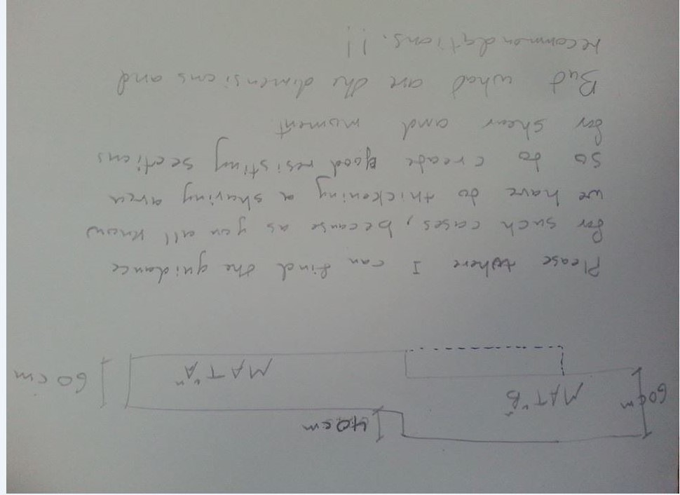
Dears;
I had a problem in a MAT foundation which is; in a part of the Mat there are two high loaded columns , that create a problem of Punching.
But I cant go in depth of the Mat, so I suggest to enlarge the column neck( The column between the slab on grade and the Mat) which is 0.5 meter in height. That solved the problem.The following questions now I have :
a. Do u agree with me????
b. I didn't design this part of column instead I reinforced it as the steel ratio of the above column. The reason that I didn't design it , is that I enlarge it around the center of the above column so no eccentricity . Do u agree??
c. And how about if it was enlarged eccentrically, Shall I add the Moment from eccentricity to the moment from analysis of the bottom of the above column and design this neck??
-
Dear Ahhhhhhh so thanks to you for your comments............. I found the solution and I want to share you all for the benefits :
I am very happy now ...
Related to LONG TERM DEFLECTION
What Mr Rana Waseem said is correct But applicable only if the moments in the slab are over the cracking moment i.e. cracked section is there. Here if we increase the tension steel that will lead to less deflection.
Now if the moments are less than the cracking moment then the whole section works i.e uncracked section. in this case no need for increasing the tension steel because already all the section works.
Now we want to reduce the deflection by putting compression steel :
1. I tried to increase the compression steel only but that doesn't work.
2. I tried to increase the tension and compression steel simultaneously that worked successfully.
Now the reason for that is (As I find it from a structural book) that:1.When the tension reinforcement is little then the compression area of concrete section against it, is small in depth, also due to cover, that leads to case 1 and hence the compression steel may be located below neutral axis (in neglected concrete area) so it will not work as compression steel resulting no reduction of deflection.
2. When increasing the tension steel the compression area of concrete is increased in depth then allow for the compression steel to be effective and it will work to reduce the deflection ( i.e CASE 2)
Summary :
In case of that the moments in slab is small (under cracking moments) then increasing the tension steel is not the solution and it will not reduce deflection. Instead of that you have to make use of the compression steel to reduce deflection but to make it work you have to increase tension and compression steel simultaneously.
-
ALL are Busy!!!

-
Can anyone share this issue to find the answer please!!!!
-
Dear...
enlarge the thickness of shear wall (because of earthquake ) may be torsion is the first mode .
Otherwise but other shear walls to avoid thickening of shear walls
tell me if that works please.
Regards
-
Dear
Sorry to disturb you too much. But this issue I am speaking about is so strange.
Really I agree you with all you have mentioned above. When we increase the Top steel in cantilever it will decrease the deflection in a good manner. and the compression steel will be reduced slightly compared with top steel addition.(I make sure by an example I did)
BUT THE IMPORTANT ISSUE that will make me CRAZY and need scientific interpretation is WHY in MY SLAB when I increase the steel at top of cantilever the deflection increased also, Is that related to the CRACKING MOMENT???
May be because the moments are small than cracking moment and in this case no meaning for increasing the tension(top) steel because already the whole section is still uncracked. please Help!!!!
But I noticed that when increasing the top and bottom steel simultaneously the deflection decreased .
-
Dear;
I confirmed this. As I mentioned in CASE 1, I have chosen the reinforcement to be from F.E the deflection was 46.7 mm at the end of cantilever. here In this case the program will use not 0.00256(T12@20) instead it will use F.E results because it is bigger 0.00285(T14@20).
Now I want to solve this high deflection in CANTILEVER .But My question now is how to solve it by increasing steel?.
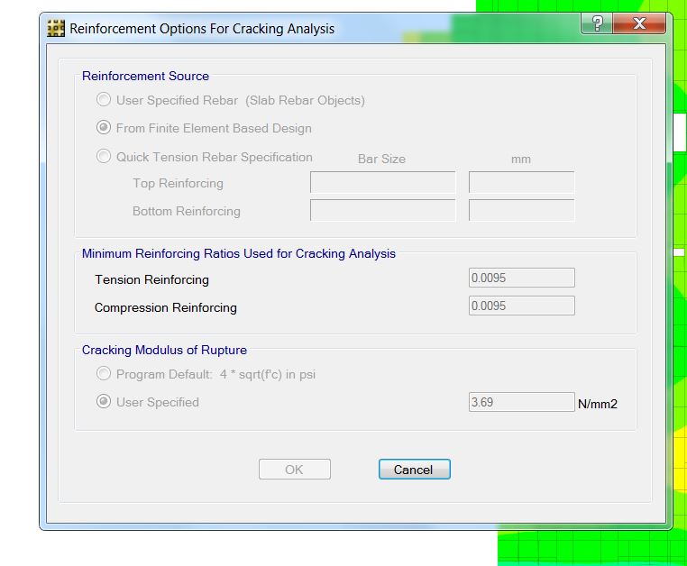
1. As far as I know if I put here a bigger min. ratio =0.0095 for the tension(TOP) and compression(BOTTOM) steel simultaneously,
the deflection decreases to 31.5 mm .
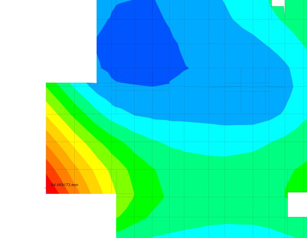
2. As My Engineer Told me, he want only to increase the tension steel (TOP)[ i.e. I put in the min. tension steel box the ratio =0.0095 and min. compression steel ratio = 0.00256 ], But I checked what he said and the result where
increasing deflection instead of decreasing. (deflection =54.5 mm )
Please provide me your way to decrease the deflection using steel in Cracking Analysis. I am sure from what I did because I checked it on many examples I know and on the Manual verification example of SAFE.
I will send you the SAFE FILE upon request .
Regards -
Dear ;
Thank you. But I am speaking about cantilever so the top reinforcement is tension, and the bottom is compression.!!!
Regards -
Dear all;
I have a very very important issue that related to long term deflection (Cracking Analysis) Using SAFE.
I Argued with another Engineer High experienced.So please help me.
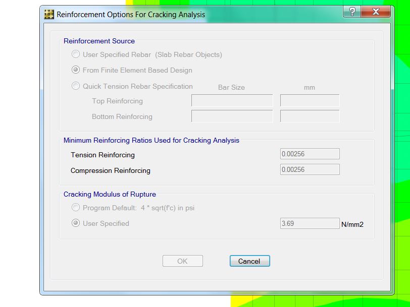
I am designing a slab 300 mm thick with 2.8 meter Cantilevers.1. CASE 1 :I want to see the results if I put only the mesh reinforcement T12@20cm.
I read the results from SAFE as in Figure 1, deflection = 46.7 mm. (I used the
reinforcement source from finite element and minimum reinforcing ratios for tension and
compression 0.00256 i.e T12@20cm see figure 2).
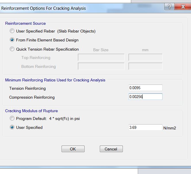
2. CASE 2: Now I want to put additional reinforcement to control the deflection.(HERE THE POINT
WHERE WE ARGUED ABOUT). I said that I have to put additional reinforcement in tension and compression =T16@10cm , that means I put in min. reinforcing ratios (in SAFE) Tension and compression =0.0095 see Fig. 3 ) In this case the deflection become 31.5 mm) see Fig. 4.
3. CASE 3 : He said that we will put only additional steel T16@10cm in the tension face . But I
checked that on SAFE (I put min tension =0.0095 and min compression = 0.00256(the main mesh (see Fig.5) ). The deflection at the contrary increased to be 54.5 mm (Fig. 6)
Question To You Dears:
What is the right procedure ? that what I did Or What the Engineer did?


-
-
Thank you Sir too much.You did me a great favor. But I still need the rule of thumb or the standard that control the width of this sharing area (100cm). Can you dear?
Regards
Mohammad
-
Thanks dears.
But can you make a quick draw showing such dimensions at the transition area.
Regards -
Dears seniors;
I have an urgent issue I need your help all.
The issue is that I want to make a MAT like in the picture please see the problem interpretation in the picture.
-
Dear Engineer;
You have to check deflection against service load combinations. but I don't know why you need to use nonlinear cracking analysis ? Do you need that to check deflection?
Regards


Punching Shear Of Shear Walls In Case Of Eq "important Issue"
in Concrete Design
Posted
Dears ;
But I still not satisfied and please look at the attached figure. that one is clearing my opinion.
See the statement that says : seismic forces tend to push the shear wall over causing an overturning moment.....that means the connection area of the slab connected to shear wall will also rotate due to that moment so because of that it behaves the same as if the moment coming form gravity loads...causing punching so we shall check punching due to seismic loads !!!!! Am I right??