

Ahmed1
-
Posts
8 -
Joined
-
Last visited
-
Days Won
4
Ahmed1's Achievements
")
Newbie (1/14)
9
Reputation
-
 Ayesha reacted to a post in a topic:
Girts and Purlins affect of Column Beam Effective Length
Ayesha reacted to a post in a topic:
Girts and Purlins affect of Column Beam Effective Length
-
Ayesha reacted to a post in a topic:
Girts and Purlins affect of Column Beam Effective Length
-
UmarMakhzumi reacted to a post in a topic:
UVL Beam Slope Equation
-
Hi, From y=mx+b you will get slope (m) for a straight line. You need to write equation for deflection curve. Take differentiation of the equation of the deflection curve and boundary limits to get slope at each end. See attached sheet. UVL.pdf
-
Salma Jabeen reacted to a post in a topic:
Girts and Purlins affect of Column Beam Effective Length
-
Salma Jabeen reacted to a post in a topic:
Girts and Purlins affect of Column Beam Effective Length
-
Salma Jabeen reacted to a post in a topic:
Girts and Purlins affect of Column Beam Effective Length
-
Girts and Purlins affect of Column Beam Effective Length
Ahmed1 replied to Salma Jabeen's topic in Steel Design
Rafters are subject to axial loads. I don't have practical calculations in hand, the attached scanned pages from a book may help you. Untitled_29082018_173346.pdf -
Girts and Purlins affect of Column Beam Effective Length
Ahmed1 replied to Salma Jabeen's topic in Steel Design
@ MA123 This factor will depend on end condition of the member. Increasing to 1 will reduce axial compression capacity for buckling. @ Ayesha I was referring to axial compression capacity for buckling (Ncy) required for checking the member for combined actions.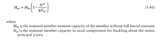
-
Girts and Purlins affect of Column Beam Effective Length
Ahmed1 replied to Salma Jabeen's topic in Steel Design
Yes purlins and girts provide lateral restraint to rafter and column, respectively.. Rafter · For calculating minor axis compression capacity, the effective length of the rafter is taken as the maximum spacing between the purlins. · When the rafter’s top flange is in compression the effective length of the rafter is taken as 0.85 x purlin spacing for calculating out of plane capacity. Column · For calculating minor axis compression capacity, the effective length of the column is taken as the spacing between the girts. · When the column’s outside flange is in compression the effective length of the column is taken as 0.85 x girt spacing for calculating out of plane capacity. -
 UmarMakhzumi reacted to a post in a topic:
Concrete Cylindrical Stregnth
UmarMakhzumi reacted to a post in a topic:
Concrete Cylindrical Stregnth
-
fc’ used in strength design is uniaxial strength of concrete. Compressive tests on concrete specimens (cylinder or prism) with L/D=>2.0 (length to diameter) closely resemble uniaxial condition in the central part. Due to multiaxial stress conditions (i.e. lateral restraint at the top and bottom platens), compressive strength of standard cube specimens (150mmx150mmx150mm) will generally be higher (1.4 to 1.1 times) than standard cylinder specimens (150mm dia x 300mm height). Depending on the maximum size of aggregate (1/3 diameter of mould), smaller size cylinders (100mm dia x 200mm height) are allowed for testing in various standards. Compressive strength of specimens smaller than standard size will generally be higher. For 100mmx200mm size cylinder no correction is required due to small variation in strength (4%). This variation can be reduced by moulding 100mm diameter cylinder in two layer. If L/D ratio of the tested cylindrical specimens is other than 2 then correction factor will be required. Cylindrical specimens with L/D ratio less than 2 will show higher compressive strength. Therefore, the correction factor will be smaller than 1. In-situ strength are generally lesser than laboratory cylinder strength due to various reasons such as size, loading rate, curing method etc. In-situ strength is generally taken as 0.9fc’. In the design strength of 0.85fc’ the factor of 0.85 includes difference in insitu and cylinder strengths and the ratio to convert stress distribution to rectangular Whitney block. In BS 8110 standard, design strength is taken a 0.67fcu. The factor of 0.67 includes difference in insitu and cube strengths, difference in cylinder and cube strengths and the ratio to convert stress distribution to rectangular block. For details on compressive strength testing you can refer to ASTM STP 169D : Significance of tests and properties of concrete and concrete-making materials.
-
imranjam reacted to a post in a topic:
Modelling pile subgrade reaction
-
Please refer to Section 16-15 of Foundation Analysis and Design by Bowles. You can keep subgrade reaction constant or vary depending on the type of material. Subgrade reaction values will be different for sand and clay. Sandy material will have higher values. Also the values will depend on strength of sand and clay materials. You may also like to review the method developed by Lymon C Reese for the analysis of laterally loaded piles. Please refer to Single Piles and Pile Groups Under Lateral Loading by Lymon C Reese and Van Impe. There is a program LPile based on the method developed by Lymon C Reese
-
High Loads under Columns and Bearing Capacity Failure
Ahmed1 replied to muneeb1213's topic in Foundation Design
Hi Muneeb, I am not really into structural design. Other experienced structural engineers on this forum can suggest you regarding raft stiffness. I understand that the Navg is 5 blows/300mm penetration with N ranging from 4 to 7. This value is still good for sandy soils supporting a raft foundation. What I understand that the pressure per storey on a raft (covering the entire footprint of the building) will be in the range of 12.5 to 15kPa (Foundation Design by Tomlinson). As you are constructing a four-storey building the contact pressure should be in the range of 50kPa to 60kPa. Therefore I am not sure why you need to extend the raft by 9' (2.7m) on each side. Regards, Zia -
UmarMakhzumi reacted to a post in a topic:
High Loads under Columns and Bearing Capacity Failure
-
High Loads under Columns and Bearing Capacity Failure
Ahmed1 replied to muneeb1213's topic in Foundation Design
Hi Muneeb, The N value you provided is at the surface or average N over the influence depth? For raft foundations on sandy soils, bearing capacity from shear failure point of view is not a problem. If you see the bearing capacity formula q=cNc+0.5*Unit Wt*B+qNq the middle term has B, which could be quite high for rafts. Also empirical formula for mat foundation is 20N (kPa) (if I remember correctly from Meyerhof). Therefore for your case the bearing capacity is in the rage of 100kPa (As Engr Uzair suggested bearing capacity value you are using is quite low for sandy soils). Important thing for you would be to check settlements. Please refer to Bowles book for settlement calculations. If settlement are high then you can consider using piles (screw piles would be a good option in sandy soils) under columns. Regards,- 12 replies
-
- 1
-
-
- foundation bearing failure
- foundation
- (and 1 more)