

Fawad
-
Posts
11 -
Joined
-
Last visited
Content Type
Profiles
Forums
Events
Posts posted by Fawad
-
-
@Rana Please explain the Pattern Live Load Factor effect on design of beam bottom reinforcement.
On 11/8/2019 at 1:28 AM, EngrJunaid said:Dear @Saiful Islam Zaber
Please see this link https://wiki.csiamerica.com/display/kb/Pattern+live-load+factor and the picture attached.
Hope this will suffice your query.
wouldn't the bottom design reinforcement for a continuous beam be very high/conservative than that required based on analysis, if calculated based on wl2/8 ???
-
17 hours ago, Rana said:
Maximum reinforcement in beams (flexure only members) are controlled by maximum net tensile strain. The above-mentioned limit corresponds to 8% max reo (4% on each side), similar to column.
Beams usually have reo less than 2%. If you are trying to put more reo in a beam using ETABS, change that section property from beam to column. I always love the idea of putting beams as columns in ETABS.
A frame section in ETABS defined as a 'column' will be designed for flexure in both direction + axial loads, a true interaction diagram. If defined as beam, ETABS wil ignore any axial load (if present) in beam design.
@Rana very well explained ... Thank You
-
Just now, Husam Al-Mufarji said:
I done a trail and I got correct soil pressure on the footing as you can see on the attachment.
I also attached ETABS trail file for your reference.
If you still did not figure out the solution, please upload your model, so I can see what is the problem.

Thank you @Husam for your efforts and sharing your Trial model.
I have checked the model and few questions to ask.1) Normally we have only bearing capacity available from client to design foundation. So how to calculate Area springs value from that bearing capacity.
2) Your model is not calculating Punching Shear. It displays N/C.3) Please explain the Isolated Column Footing and soil profile options given in Define ---> Spring Properties ---> soil profile and isolated column footing.
Thanks
-
Need clarification regarding difference in ETABS analysis and design moments.
Why ETABS design & analysis moment under the same combo i.e UDCON2 is different. (See photo attached)
Moment diagram shows 1809 kip-ft while ETABS is taking 2590.69 kip-ft for reinforcement calculation.
The design moment is also different from the envelop combo i.e 1809+642=2451 kip-ft
Thanks

-
On 3/27/2019 at 11:29 AM, asadishaq said:
Shrinkage strips are temporary joints that are left open for a certain time during construction to allow the shrinkage to take place without inducing stresses.
It is usually 2 to 3 feet wide across the entire building and should be cast 2 to 4 weeks later than the adjacent portions.
Thank you @asadishaq
Is there any code reference for shrinkage strip ??
Architect is not allowing for any expansion joint in a plan of area 80mx50m.
Normally grid to grid spacing is 12mx12m panel over the area of 80mx50m.
Thermal expansion of 80m long concrete comes approx 32mm with 40 degree Centigrade change in temperature. Coefficient of thermal expansion of concrete is 9.9e-6 per degree centigrade.
i.e (80x1000)(40)(9.9e-6)=32mm
I have provided top reinforcement more than required at the roof slab and provided an expansion gap of 100mm in my 80mx50m structure with nearest existing building.
Am i doing it right ???
-
On 11/1/2017 at 12:04 PM, waqar saleem said:
if concrete dimension is 150ft-200ft, it is advisable to provide expansion joint or shrinkage strip to avoid shrinkage/temperature cracking.
What is shrinkage strip ??
-
How to check this limit of 1.4 in ETABS.
-
Thank you @Engr Junaid,
-
Thank you sir @BAZ,
As all my other serviceability checks like drift and deflections are in code allowable limit, so i just amplified/override the eccentricity of my EQX and EQY in load pattern by torsion amplification method as per UBC97 and designed my vertical members accordingly.
Please guide/correct me if i am missing something.
Jazakallah
-
Aoa,
Thank you all the seniors for providing such a nice learning platform.
I am working on the design of a 3 story structure (2 basements+Ground Floor). Base level is at -10m from grade level while top roof (ground top) is +8m from grade level.
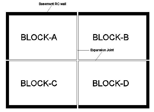
Total covered area of building is 100mx60m which is divided into 4 blocks i.e 50mx30m each (See pic attached). Basement retaining wall is provide only at two orthogonal sides (one long and one short side) of each block. But this two sided retaining wall is creating extreme torsion irregularity in my structure. Normal span length is 12m.
So my question is that can i ignore this two sided basement wall in my model ? because this is below grade level and would not contribute in resisting EQ.

DOUBLY BEAM DESIGN IN ETABS
in Software Issues
Posted
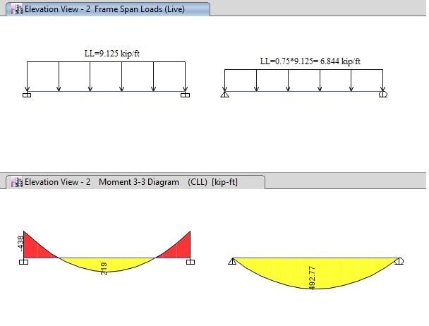
1) ETABS calculate Positive moment by taking 75% of Live load plus full dead load but my point is that if our applied live is huge like 200psf and Dead load (finishes Load+Slab self wt) is 150 and having long span of about 35ft. The positive design moment will be very much conservative because of the difference in wL2/8 and wL2/24. So if we reduce the PLLF in ETABS from 0.75 to 0.5 or less. Would this approach will be correct ?????
Thanks for your time & guidance..