Iftikhar Hussain
-
Posts
17 -
Joined
-
Last visited
Iftikhar Hussain's Achievements
")
Newbie (1/14)
2
Reputation
-
 Iftikhar Hussain changed their profile photo
 -
User Define Plastic Hinges Properties ETABS/SAP...
Iftikhar Hussain replied to Iftikhar Hussain's topic in Software Issues
YES BROTHER.... BUT USING FRP OR FRP+STEEL REINFORCED SECTIONS... -
 Iftikhar Hussain reacted to a post in a topic:
User Define Plastic Hinges Properties ETABS/SAP...
Iftikhar Hussain reacted to a post in a topic:
User Define Plastic Hinges Properties ETABS/SAP...
-
ASSALAM o ALIKUM. Once i found a very good discussion of above topic considering beam as a column section in etabs. As in beam we are normaly neglecting axial forces while assigning beam as a column section will consider this contribution of beams in a structure. can anyone please direct me to that discussion or can shear the exact behavior of beam as a column. i considered beam as a column while kept all other parameter same (reinforcemnt and section as same as a beam) and anlyse by pushover. Pushover curve was same in both cases but formation of plastic hinges in beam (as a column) was less than considering beam as a beam section. even though i assigned auto M3 hinges in both cases.
-
User Define Plastic Hinges Properties ETABS/SAP...
Iftikhar Hussain replied to Iftikhar Hussain's topic in Software Issues
SIMPLIFY WHITENY APPROACH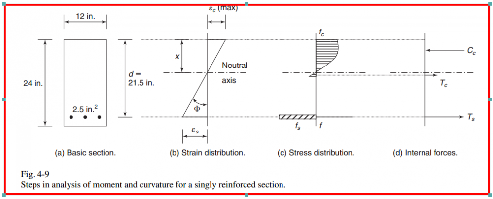
-
User Define Plastic Hinges Properties ETABS/SAP...
Iftikhar Hussain replied to Iftikhar Hussain's topic in Software Issues
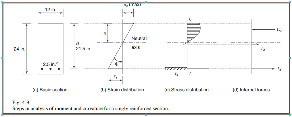
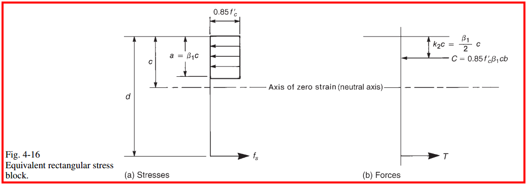
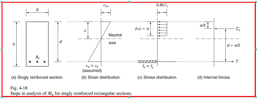
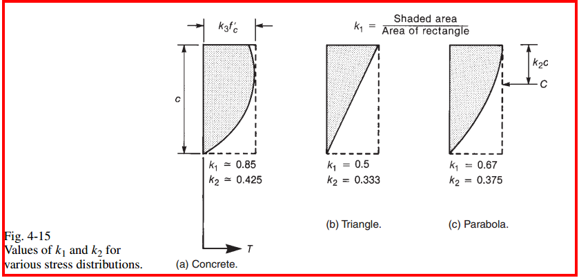
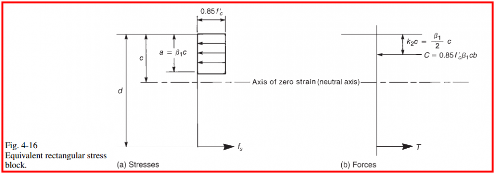
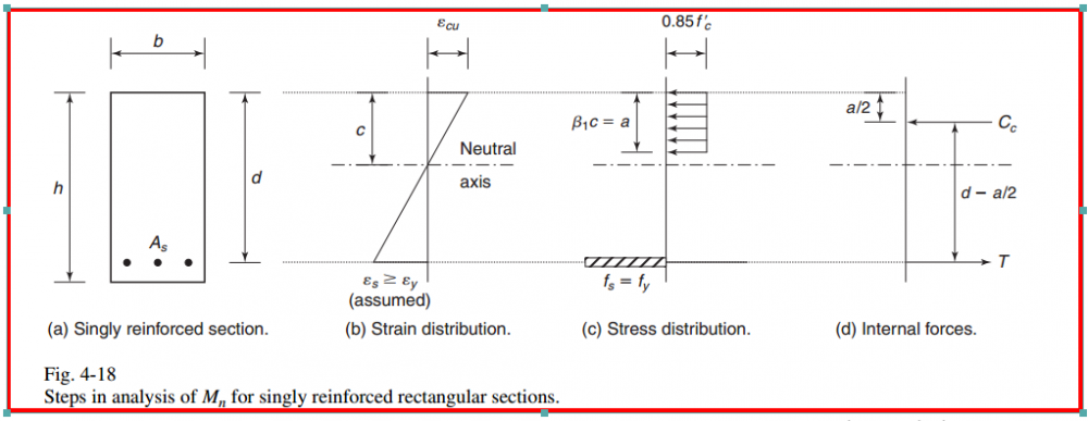
Thank you for your response brother... Is SECTION MODIFIER of etabs and sap2000 is give same results as EXTARCT. As i know in calculation of moment interaction ETABS uses WHETINY strees strain curve considering equivalent rectangular block for stresses in concrete and and in moment curvature it ignores moment after yielding... but i am not sure about EXTRACT. -
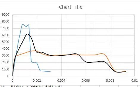
ASSALAM O ALAIKUM. HERE IN ATTACHED FILE, THERE are MOMENT CURVATURE AND MOMENT INTERACTION DIAGRAM FOR steel rc section, frp rc section and steel+frp rc section. FROM THESE OUTPUT SECTION DESIGNER RESULTS WE CAN SAY IT IS ACCEPTABLE(IN GENERAL)... but values for the moment in MOMENT INTERACTION for the same section reinforced with steel and FRP are also same, while there is a very little change with steel+frp reinforced section... would it be ok to just consider the results of MOMENT CURVATURE DIAGRAM WhILE IGNORING MOMENT INTERACTION diagram results.? AND ALSO how can we consider these results in defining (user) plastic hinges for beam and column? Section designer ETABS 1.pdf
-
HELLO. HOPE Everyone is doing well.. Can any one please elaborate that how can we introduce user define plastic hing for beams and columns as the DATA extracted from Moment curvature diagram is different than the data required for user define plastic hinges?
-
 Iftikhar Hussain reacted to a post in a topic:
UBC 97 Response Spectrum Seismic Provisions
Iftikhar Hussain reacted to a post in a topic:
UBC 97 Response Spectrum Seismic Provisions
-
Pushover and Response spectrum analysis?
Iftikhar Hussain replied to Iftikhar Hussain's topic in Seismic Design
sir, i analysed my model (ESA) prior to check its drift limit i designed it by ETABS, checks show all the member satisfied the analysis result. to check its performance level by pushover (formation of plastic hinges and slope of PO curve are also show ductile behavior) but the drift limit in first stage (analysis) crosses the limit of code. as it is recommended to increase section dimension( while increasing x.sec of columns and beams not affected it to much) now how can i control this drift limits. thank you -
Pushover and Response spectrum analysis?
Iftikhar Hussain replied to Iftikhar Hussain's topic in Seismic Design
thank you sir for your response. It means that first we have to annalyse our structures according to code provisions (RSA and ESA) and than we can check their capacities through Pushover analysis. if i am wrong let me correct. -
Iftikhar Hussain reacted to a post in a topic:
Pushover and Response spectrum analysis?
-
AOA. Hope you all are doing good. Is it ok to Analyse a Moment resisting frame By pushover prior to the design of frame? if yes than whether it is neccessory to apply checks of drift and displacement on frame during static analysis? if both of the above cases are true than what would be the analysis results of Pushover Analysis (other than pushover curve) to check whether the results are ok or not. In my case i have to Analyse a MRFs for different earthquake loads, so how the check to compare the results of ESA, Pushover and response pectrum analysis.. thanks in Advance. ETABs will be used for structural analysis and design.
-
ILYAS reacted to a post in a topic:
Modeling of FRPs Bar in ETABS
-
ILYAS reacted to a post in a topic:
Modeling of FRPs Bar in ETABS
-
Modeling of FRPs Bar in ETABS
Iftikhar Hussain replied to Iftikhar Hussain's topic in Software Issues
yes sir, i know about ACI 1R 440 for designing FRP reinforced flexural members, According to ACI frp is still not approved for compression member due to its anisotropic behaviour. Canadian Code for FRP i think provide complete design guidlins. -
Modeling of FRPs Bar in ETABS
Iftikhar Hussain replied to Iftikhar Hussain's topic in Software Issues
yes brother, i am doing my Master from SEU. -
Would it be possible to model concrete member reinforced with FRPs bars (i.e. GFRP, CFRP OR BFRP)? and also guide could we import "section model" or " FRP model" file(matlab ) TO ETABS for analysis? i have read somewhere on CSI Web that the only option is its equivalent modeling in such way that extra steel bars used in beam to model the glass fiber as a replacemt of FRP to incresea the beam strength? is it possible to do so. S
-
BFRP bar as main reinforcement in concrete
Iftikhar Hussain replied to Iftikhar Hussain's topic in Software Issues
thanks for your concern...Actually FRPs have different sort of responeses in term of deflection, shear and momemt (in concrete). Similarly having different mechanical property than steel. For FRPs ACI 440 IR 06 have fixed some reduction factor which should be consider during designing of structure exposed to different environmental impacts. ETABS and SAP2000 till now not compatible to design members reinforced with FRPS. while high strength steel us on another side. ETABS version upto 9.7 were start giving same if you increase tensile strnght of steel more than 80ksi. but for new version i m not sure.. here for this particular case i think the only solution is to model FRPs material or section reinforced with FRPs and import to ETABS. -
BFRP bar as main reinforcement in concrete
Iftikhar Hussain replied to Iftikhar Hussain's topic in Software Issues
thank you sir.... it helps alot -
BFRP bar as main reinforcement in concrete
Iftikhar Hussain replied to Iftikhar Hussain's topic in Software Issues
ok,,, have you ever try this... if you have ETABS let me share some snap from there how can you modified steel properties to BFRPs. thanks in advance