

Zain Saeed
-
Posts
31 -
Joined
-
Last visited
-
Days Won
8
Content Type
Profiles
Forums
Events
Posts posted by Zain Saeed
-
-
On 4/7/2021 at 9:24 AM, ILYAS said:
Please solve one frame manually with these conditions ,you will understand
any guidance for understanding the manual application of live load on top of the slab ..UDL or point loads ??
-
While defining "Mass source" in ETABS for overhead water tanks, do we need to consider complete water load (defined as live in ETABS load pattern) ??? and what are provision in code for its importance factor (1 or 1.25 )
Secondly i have bracing beams (12x18) in rectangular OHWT and i am getting very high top and bottom steel (4.3 inch2) coming in them from ETABS against the load combo 0.9 dead + 1.43) Earthquake (modified load combo as per ACI 350). any idead how to tackle this
-
On 1/7/2019 at 1:17 PM, Engr. Salman said:
Dear Major!
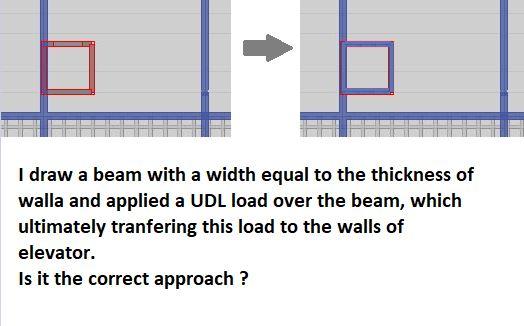
How will I apply the UDL over the walls of the Elevator? There are three options in assigning a load to a building component as shown in the attached picture i.e Shell, Frame, and Point load, then how will I apply the load over the walls?
I have an idea for applying UDL over walls. If I draw the beams over the top of the wall and apply the UDL load over the beams as shown in the attached picture. Is it the right approach? or I should find another way?
.thumb.png.df306ec36ec5bea0ae312803d20ee9c6.png)
The top of shaft will be having a slab and why not applying area load on it ???
-
On 6/24/2019 at 10:46 PM, abbaskhan2294 said:
Once u have added bracing elements in between the frames now its upto you how u consider ur structure to behave either as Building frame system or dual system.
My recommendation will be to use building frame system in Zone 1 ,2A and 2B and go for dual system in siesmic zone 3 and 4.
Furthermore if u r going for building frame system modify the moment of inertia about x and y directions in the section modifiers of the columns as 0.1 for both x and y directions.
If u r going for dual system let the section modifiers be as for moment resisting frame. Compute the total base shear and the base shear shared by the column. If the base shear shared by the columns is less that 25% of the total base shear you need to amplify the base shear.
Again how you can amplify it?
E.g : If base shear shared by the columns comes out to be 5% of the total base shear, go to load cases and for Earthquake loads in x and y direction change the factor to 5 as 5x5 = 25. and when u rerun the model design the columns for 25% of the base shear.
Again another thing to note is that use the first model with no earthquake load amplification for design of bracing elements and the 2nd model with earthquake load amplification is to be used for columns design only.
Hope you got it.
If we want the building structure to behave as a building frame system (gravity load by frames and lateral load by shear wall) then do we need to make sure while modelling that none of the beams are resting on the wall and transfering the gravity loads as well to them ??
Secondly as you suggest "Furthermore if u r going for building frame system modify the moment of inertia about x and y directions in the section modifiers of the columns as 0.1 for both x and y directions.:" reducing the moment of inertia in both direction will not reduce also the axial load carrying capacity ??
-
Is there some way to convert V19 ETABS file to lower ETAB9.7.4 ???
-
Is there someway in ETABS higher version to view this non uniform load like a triangular load or contours to ensure that the load applied is accurate or not
-
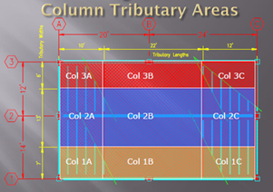
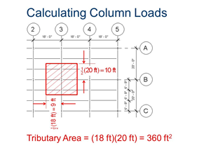
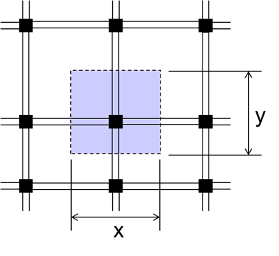
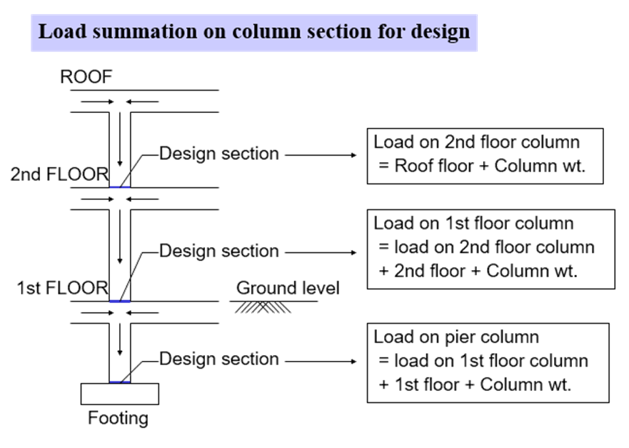
The images below are self explanatory for the tributary area method. I use this method to find the size of the column in a multistory building

-
On 4/18/2018 at 9:46 PM, Fatima Khalid said:
Being a civil engineer, we learn how to design RC structures which consists of beams and columns. what about load bearing structure? Where can I get information regarding design of brick masonry structure that is common practice in most part of Punjab... And can we model it on Etabbs and check pier and spandrel forces, etc?
I believe the attached document would give you a little guidance to overall manual design process in load bearing residential homes
-
5 hours ago, Hamza Ahmad said:
Sir, for checking story stiffness manually we will use Story force ( Vx or Vy ) or Auto seismic forces (Fx or Fy) from etabs ??
Hamza i checked and confirmed from ETABs higher versions that its the story shears Vx or Vy we have to use for calculation of story stiffness
-
On 3/15/2015 at 12:32 AM, kHURRAM ALI said:
can somebody explain how to design load bearing strucuter , what software i should use?
Manual calculations are mostly performed and excel sheets are used to design conventional load bearing masonry structures
-
I havent seen a dedicated book for the conventional design of masonry structures. However, most of the material related to conventional load bearing structure design in Pakistan is summarized in document below
-
14 hours ago, hali said:
AOA everyone.
I just wanted to know, is the ACI coefficient method for analysis of two way slabs still valid? Or some other method is preferred over this one?
Regards,
HA
Direct Design Method (DDM) is the preferable method for designing the conventional two way slab system and other floor system like flat slabs and flat plate slab system. The ACI coefficient method is declared obsolete because the end results are more conservation (more factor of safety). However, still this ACI method is commonly used in most of the design offices for designing two way slab system.
NOTE: ACI coefficient method is not used for designing flat slab or flat plate slab system.
- Ayesha and UmarMakhzumi
-
 1
1
-
 1
1
-
3 hours ago, UmarMakhzumi said:
Shear is generally resultant for force at a given point. Like beam shear is sum of all forces at a section.
Similarly Story Shear refers to the net lateral load at a floor. ETABS might be defining story forces as net forces at a level and story shears as individual seismic shear for each floor (the opposite way). They can define it how they want, as long as they are referring to the same concept.
Displacement has to be absolute as we are interested in stiffness. If you were interested in any serviceability limit state, then it could be relative for that limit state. But for stiffness, its absolute to base.
Thanks.
I checked and found that in ETABS 9.7.4 version after analysis when you export the summary report, it gives you Story Forces under two different heading which are as follow:
1- Auto Seismic Story Forces (Fx, Fy, Fz) >> Here Fx and Fy are the individual seismic shear values at each level or absolute seismic force values at each floor level.
2- Story Forces (P, Vx, Vy) >> Vx and Vx are the sum or net values (Story shears) and ETABS uses these (Vx and Vy) along with the total floor displacement for calculation of story stiffness
Thanks once again Omar bhae ...
-
2 hours ago, UmarMakhzumi said:
Shear is generally resultant for force at a given point. Like beam shear is sum of all forces at a section.
Similarly Story Shear refers to the net lateral load at a floor. ETABS might be defining story forces as net forces at a level and story shears as individual seismic shear for each floor (the opposite way). They can define it how they want, as long as they are referring to the same concept.
Displacement has to be absolute as we are interested in stiffness. If you were interested in any serviceability limit state, then it could be relative for that limit state. But for stiffness, its absolute to base.
Thanks.
Thanks Umar bhae for the explanation. i got your point very clear now. il definately gona look in to ETABS help to confirm what it means actually by Story forces either the absolute value or net value at a given floor level.
-
On 2/13/2019 at 12:50 AM, UmarMakhzumi said:
You have raised a good point. Generally stiffness is applied force/ displacement for force required for a unit displacement.
For seismic or any lateral loads, the loads sum up as you go from top to bottom. For for top floor, the stiffness is:
Force at top floor/ displacement
However, for the level below, the stiffness would be:
Sum of Top Floor and level below lateral forces / displacement of that level.
")
Let me know if this is still not clear and I can provide another example.
Cheers!
Its looks a bit strange. Actually i have been using the story forces from ETABS summary report and not the Story shears for finding this story stiffness thing. It would be better if you can elaborate it with some example to clarify my thoughts. I have the understanding the as we are taking the absolute floor displacement and not the story displacement in the stiffness calculation and this displacement should be because of the story force and not the story shear which is sum of forces coming from all above stories
-
On 1/9/2013 at 1:03 PM, asadishaq said:
In ETABS's show response table , why story stiffness is always zero?
kindly tell me
If you are using ETABS 2015 or higher version then Go to Analyze tab > Set load cases to run > tick or activate the option for "Calculate Diaphragm Center of Rigidity"
-
On 1/8/2013 at 1:22 AM, UmarMakhzumi said:
Story Shear/ Story displacement
Umar bhae shouldn't be it story forces instead of Story shears ??? and the denominator as absolute maximum displacement of floors.
-
Can we have the formulae as mentioned by Mam Fatima and Mam Areeb. i would really appreciate it. i am making an excel sheet for various seismic checks and the information above would be really helpful.
Thanks
-
On 5/25/2017 at 3:20 AM, Steel said:
No sir.. it is present in etabs 2016... i found it later....
Share the screen shot where you find this option in ETABS 2016.
-
On 6/11/2018 at 5:05 AM, Areeb said:
Hello Zain
The method which you have mentioned above is for finding out whether the system has soft storey or not. You can use the method mentioned above or ETABS latest version directly gives the stiffness for each storey thereby its easy to find out whether the system has soft storey irregularity.
Thanks .. So for the weak storey, the method mentioned in earlier posts of Mam Fatima i.e finding flexural strength of column/wall and dividing it by their length is ok ??
-
On 5/20/2018 at 11:18 AM, Fatima Khalid said:
To find weak storey, I used to calculate flexure capacity of columns and then divide them with member length to get shear strength of the column. Then I add all the columns shear strength present in one storey to get the shear strength of one storey.
Is this method correct?
This is some thing new to me....You mean Flexural capacity (phi Mn) or the Axial load carrying capacity (Phi Pn) of column divided by length became its shear strength ?? ,,Can i have its reference
-
On 5/20/2018 at 2:26 AM, Areeb said:
Umar,
Yeah I have checked it and by discussing it with other engineers came to find out that ETABS 16 explicitly doesn't provide data/excel format for identifying the weak story. There is a table for finding out stiffness of each story thereby helping us identify Soft Storey, but Weak Story needs to be done manually. Software MIDAS provides a table in results clearly displaying Shear Strength of particular storey, but in Etabs it is not present. Yeah by using displacements of adjacent floors it is possible to identify Soft Storey, but that method is not needed now as ETABS clearly gives us Stifnesses of each storey thereby easily helping us to find out Soft Storey in a system.
Sorry, I have quoted ACI for irregularities its ASCE
Regards,
Areeb Ahmed
Can we not used this method of using the storey displacement values given at the very last section of the ETABs summary and divide these values by the storey forces to get the storey stiffness ?? and later compare the stiffness of one storey relative to other above or below it
-
For Applying loads on Basement wall this could also be done in SAP but ETABs has limitation of this ...It would be better if u design the Basement Walls using spread sheets of a very easy software named as QuickRWall
-
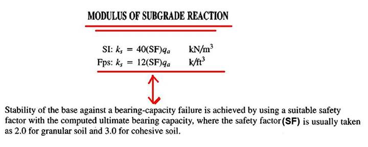
For Defining Modulus of Subgrade in SAFE see the 1st pic in attachment
As in the figure you uploaded for punching shear results it is clear that u are getting values of the ratio more than 1 which is not oK ..As far as the 5' thickness u have specified for this Raft is too much ..Kindly check the Loadings in ETABs
.png.76a12a3a940719305e1bd6ccd6011760.png)
LEARNING 100% OF ETABS FOR STRUCTURAL DESIGN
in General Discussion
Posted
Ahsan for learning basics of ETABS you can watch
https://www.youtube.com/channel/UChjVkfl09By3LvpcIZwoAzA
https://www.youtube.com/c/MunawarHussain9CivilMDC
https://www.youtube.com/c/TheStructuralWorld/playlists