M. Asad Warraich
-
Posts
18 -
Joined
-
Last visited
-
Days Won
1
M. Asad Warraich's Achievements
")


-
Book for Design of Strip Footing
M. Asad Warraich replied to M. Asad Warraich's topic in General Discussion
I know that. I was trying to find a book with field examples on how to transfer loads from slabs to beams and walls (if load bearing) and then to footing. -
Can anyone suggest me some good books/sources in which method to analyze loads, load distributions, and design RCC strip footing has been designed. I am asking for a book which discusses practical example of designing strip footing e.g. strip footing of a residential building.
-
You don't have to look at all the calculations. Just give your opinion on this part of the calculations.
-
Thanks for your comments. Actually, my purpose of sharing calculations and this post here was to get experts' opinion on if I am doing the design correctly. Would be really grateful if you can have a look at the calculations. Thanks.
-
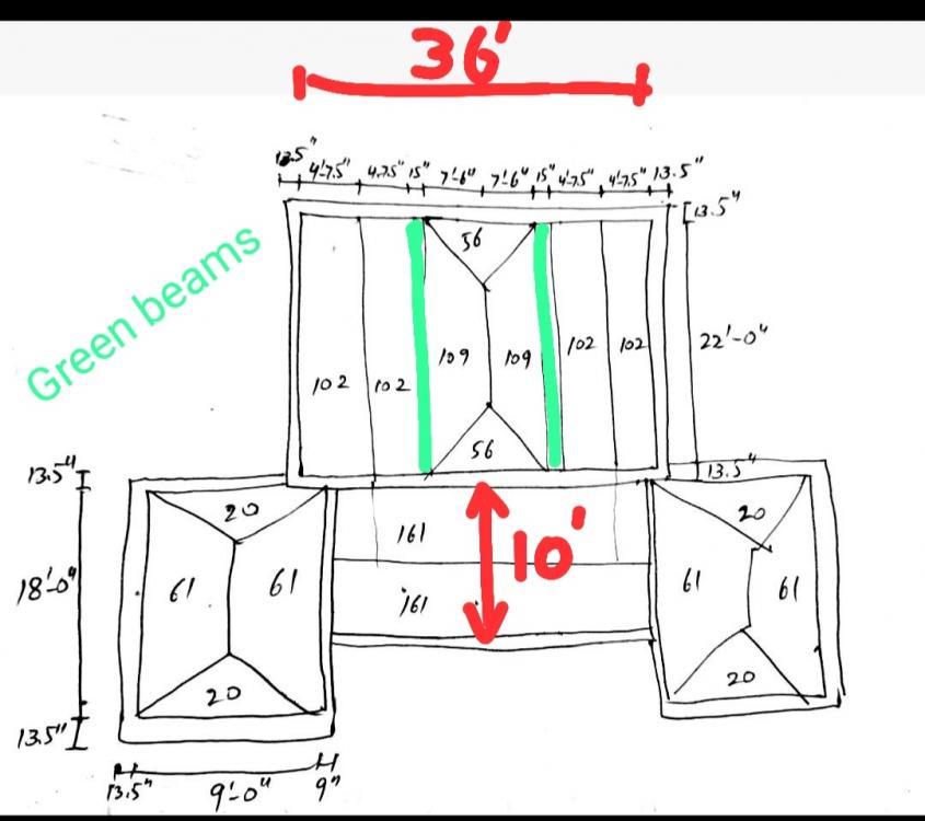
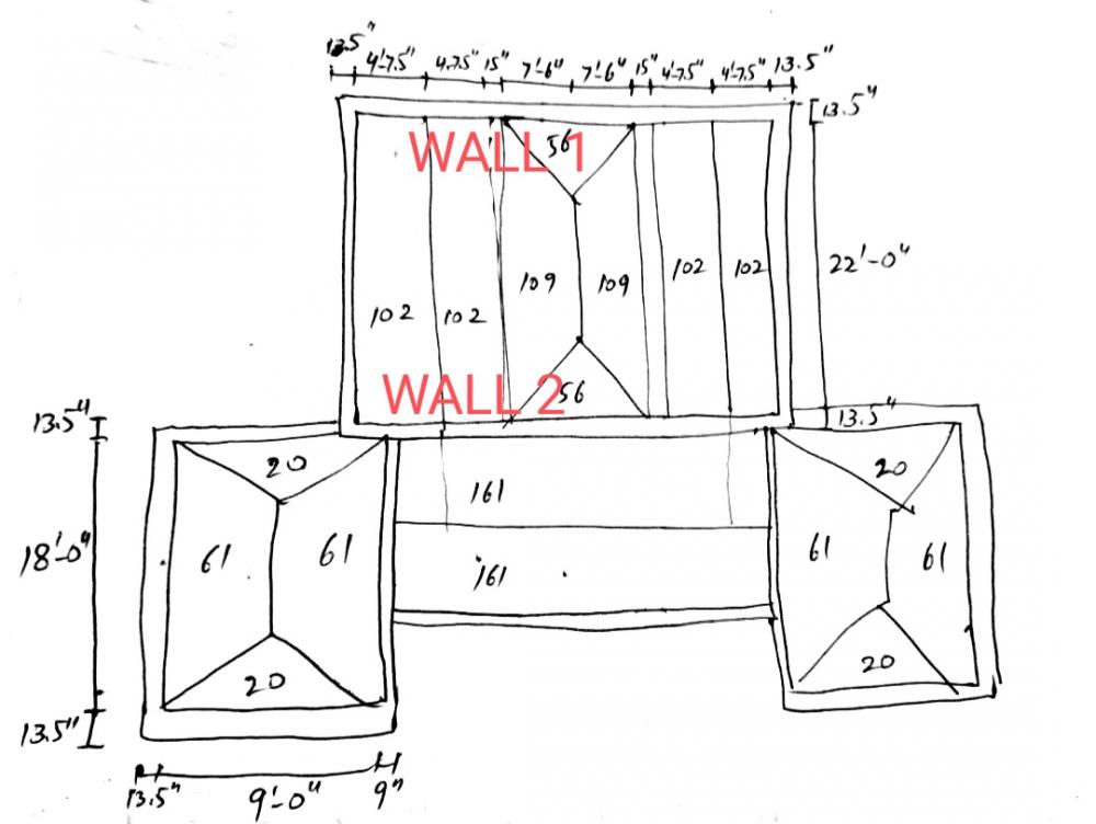
To design Wall - 1 for two storey building, I adopted this method. Please comment. LOAD CALCULATION 1- Masonry Walls Load 13.5" Thick 12'-0" High 13.5/12×(12+12)×120/1000=3.24 k/ft 2- Parapet Wall Load 4.5/12×2×120/1000=0.10 k/ft 3- Masonry Walls Load 13.5" Thick under plinth level 13.5/12×(3+3)×120/1000=0.81 k/ft 4- Floor Loads Both beams will bear load coming from slab and transfer it to their ends resting on walls as point loads. That point load will be divided by the width of the tributary area being born by both beams. Tributary Area of beams for wall - 1=102/2+109/2+109/2+102/2+56=267 Beam size is 12"×18". > Slabs Loads=65+65=130 psf Point load due to slabs' distributed loads=267×130/1000=34.71 kips Divide by width of tributary area=4+7.5/12+15/12+7.5+15/12+4+7.5/12=19.25 feet Load per unit length due to self weight of slab=34.71/19.25=1.80 k/ft > Finishes Loads=50+60=110 psf Using same procedure Load per unit length due to floor finishes=1.53 k/ft > Live Load=50+50=100 psf Load per unit length due to distributed live loads=1.39 k/ft > PL due to beam self weight 12×18/144×(22/2+13.5/12)×150/1000=2.73 kips for one beam For four beams (two at FF slab & two at roof slab)=4×2.73=10.91 kips Divide by width of tributary area=10.91/19.25=0.57 k/ft TOTAL LOADS ON WALL PER UNIT LENGTH • Total unfactored dead load=3.24+0.10+0.81+1.80+1.53+0.57=8.05 k/ft • Total unfactored live load=1.39 k/ft FOOTING WIDTH REQUIRED Wreq=(8.05+1.39) / (0.70×2.2045)=6.11 feet
-
WHY 2 WAY ACTION HERE? Because dimensions of slab in between two beams is 15'-0"×22'-0". WHY 1 WAY ACTION HERE? Because it's a verandah and its dimensions are 33'-6"×10'-0".
-
Portion between two beams is two way slab (shorter dimension: 15'-0", longer dimension: 22'-0") In main hall (36'×22'), both slabs at sides of beam is one way (9'-3"×22'-0") i.e. 102+102 tributary areas
-
You can have a look at this drawing. Green lines are two beams.
-
Floors/slabs are of RCC. In main hall, there are two beams which are resting on masonry walls (load bearing walls). In all other rooms, slabs are resting directly on masonry walls (load bearing walls). In the main hall of size 36'×22' (check dimensions), there are two beams. Portion of slab between two beams is two way and remaining two portions are one way. No using 5" slab. Numbers 61, 61, 20 represent magnitude of tributary areas formed using one way & two way load distribution concept. 65+65 means 65psf slab at FF and 65psf slab at Roof. 50+65 means 50psf finishes at FF slab and 65psf at Roof slab. 50+50 means 50psf live load at FF slab and roof slab each.
-
Aslamoalaikum. I am trying to design strip footing for a two storey mosque. I have shared load distribution in the photo. There are two beams in the main hall. I can't figure out how this load distribution can be used to design strip footing for wall 1 and wall 2. Can anyone guide me? Assume net allowable bearing capacity is 0.70 T/sft. Other assumptions All masonry walls 13.5" thick & 12'0" high Slabs: 65+65 Finishes: 50+60 psf Live: 50+50 psf Please guide.
-
In an RCC slab-beam frame structure modelled in ETABS, we reduce the torsional stiffness of a beam to 1%. This is done to redistribute the moments to slab and columns. Beam and column is automatically designed in the software. But when we will design the slab, how will we account for the additional moments that will be produced in the slab due to negligible torsional stiffness of the beams supporting it? If we design the slab using ACI coefficient method, how can we take into account those additional moments? Please guide. - Assumptions: Slab is shell with 0.25 modifiers, Beam 0.01/0.35/0.35, Column 0.70/0.70
-
I have modelled a simple four room (2×2) grid) double storey structure on ETABS. I have made following assumptions: - 12×12 Columns (MOI-2/3=0.70) - 12×12 Beams (T=0.01, MOI-2/3=0.35) - 6" Slab (Shell Thin m11,m22,m21=0.25) - 50 psf Live Load & 50 psf Superdead Load Haven't considered dynamic analysis & P-delta analysis. I have also done manual calculations of the structure. But my analysis values don't match with the ETABS results. Is it because in the manual calculations I have considered simple 45° load distribution while the slab in ETABS is shell i.e. load distribution is different for shell element. Please guide.
-
I have exported ETABS analysis results to SAFE. I want to design footing of columns in SAFE. Depth of footing is 7 feet and net allowable bearing capacity (Qna) is 0.60 T/sft. To define modulus of sub grade reaction, I've used Bowles' equation (12 FOS Qna). Structure has been subjected to seismic loads (EX, EX+ey, EX-ey, EY, EY+ex, EY-ex). Load combinations were defined in ETABS as per UBC-97. I have a few questions. Request members to answer. 1- If soil bearing pressure against certain load combinations (imported from ETABS) in analysis results is more than Qna, should footing size be increased or only allowable settlement and punching shear is to be checked? It should be mentioned here that since footing is sized against service dead and live loads, soil bearing pressure against different load combinations will always be greater than Qna. In an example in Nilson's book, a square footing is sized against service loads but bearing pressure against 1.2D+1.6L exceeds Qa. Still, author proceeds for the design and only checks against one way and two way shear. 2- If raft footing is designed, is following formula used for subgrade modulus (as allowable settlement for raft is 2"): 24 FOS Qna 3- Various load types are imported from ETABS i.e. EX, EY, EX+ey, EX-ey, DEAD, LIVE, FINISHES. To find required size of the isolated footing, are all load values in Z direction added and divided by Qna to get required area? Or only DEAD+FINISHES+LIVE is to be used for sizing the footing? 4- Is columns' stiff property thickness to be kept equal to depth of footing (Df=7 ft=84 in)?
-
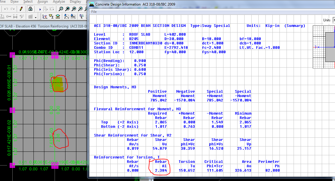
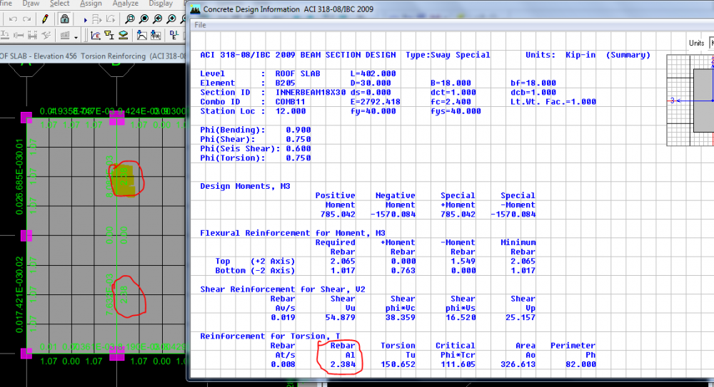
I've modelled a structure on ETABS 9.7.4. After designing the concrete frame, I checked torsion reinforcing for internal beams by following this command: Design >> Concrete frame design >> Display design info >> Design output (Torsion reinforcing) Can anyone guide me why I'm getting torsion reinforcing? I have set modifier for torsion for beams equal to 0.10
-
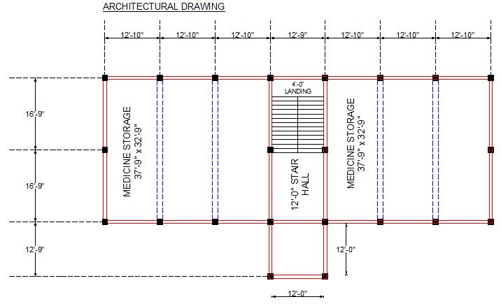
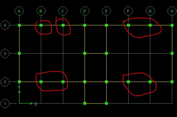
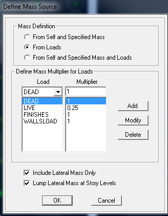
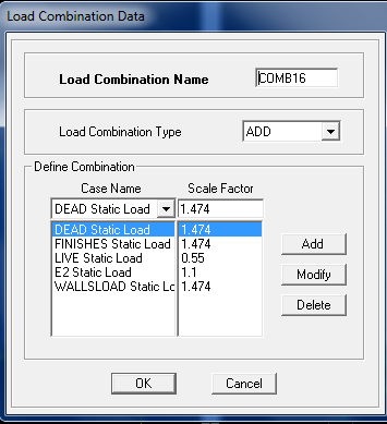
I am trying to model and design a two storey building on ETABS. It's to be used as storage for medicines. Clear height of all floors is 14'-0". I have considered these design parameters: Loads Mumty (80 PSF Finishes + 25 PSF Live) Roof Slab (80 PSF Finishes + 60 PSF Live) FF Slab (80 PSF Finishes + 125 PSF Live) Masonry Walls (9" Thick) Assumed density of 130 lbs/cft as walls shall be plastered with C:S mortar. Height = 14ft. Load = 130x14x9/12=1365 lbs/ft = 1.365 kips/ft Foor roof and mumty, since there's only 4.5" thick parapet wall of 2.5' height, calcualted and applied 125 lbs/ft load on outer beams. Material Properties fc' = 2.4 ksi for beams and slab fc' = 3.0 ksi for columns fy = 40 ksi overall Frame Sections Columns = 18"x18" (Modifiers: EOI-2/EOI-3=0.70) Beams = Red 18"x18", Blue 18"x30" (Modifiers: Torsion = 0.20, MOI-2/MOI-3=0.35) Slab = 6" (I've defined slab as shell element and applied modifiers of 0.25 for m11, m22, m12. Applied these stiffness modifiers as per ACI 10.11.1 for ultimate condition) Diaphragm = Rigid Static Load Cases Dead with self weight multiplier = 1 Live Finishes Masonry Walls Loads (self weight multiplier = 0) EQx EQx + ey (5%) EQX - ey (5%) EQy EQy + ex (5%) EQy - ex (5%) Lateral Loads Building is situated in Zone 2-B. For this zone, Z=0.20 (PBC), Profile Type = SD (as we don’t know properties of soil in sufficient detail, SD is to be used as recommended in Pakistan Building Code), Over-strength factor = 5.5, Importane Factor = 1. Mass source Live = 25% Dead = 100% Finishes = 100% Walls Load = 100% Choose 'From Loads' option. Load Combinations Followed UBC-97. I've not considered snow load and wind load. Since not considering these loads, therefore I obtain following load combinations: 1.4D, 1.2D+1.6L, 1.2D+E+L, 0.9D+E, 0.9D-E Since E=Eh+Ev and Ev=0.5 Ca I D For soil profile type SD, Ca = 0.28. Hence Ev = 0.14D. Added this factor in above equations and multiplied load combinations containing E (lateral loads) with 1.1 and obtained following 20 load combinations. I multiplied load combinations containing seismic load with 1.1 as it was recommended by Dr. Qaiser Ali of UET Peshawar in one his lectures on the seismic design of buildings. 1. 1.4D 2. 1.2D+1.6L 3. 1.474D+0.55L+1.1[Ex] 4. 1.474D+0.55L+1.1[Ex+ey] 5. 1.474D+0.55L+1.1[Ex-ey] 6. 1.474D+0.55L+1.1[Ey] 7. 1.474D+0.55L+1.1[Ey+ex] 8. 1.474D+0.55L+[1.1Ey-ex] 9. 1.144D+1.1[Ex] 10. 1.144D+1.1[Ex+ey] 11. 1.144D+1.1[Ex-ey] 12. 1.144D+1.1[Ey] 13. 1.144D+1.1[Ey+ex] 14. 1.144D+1.1[Ey-ex] 15. 0.836D-1.1[Ex] 16. 0.836D-1.1[Ex+ey] 17. 0.836D-1.1[[Ex-ey] 18. 0.836D-1.1[Ey] 19. 0.836D-1.1[Ey+ex] 20. 0.836D-1.1[Ey+ex] For example, load combination no. 04 In load combinations, E1=Ex, E2=Ex+ey, E3=Ex-ey, E4=Ey, E5=Ey+ex, E6=Ey-ex Structure was modeled on ETABS and loads were applied as assumed already. Support restraints: Fixed Tx, Ty, Tz, Rx, Ry, Rz Selected all slabs and assigned rigid diaphragm Selected all slabs and meshed auto 2x2. Analysis was run and structure was designed concrete frame. But the results I have obtained seem wrong to me. I've mentioned the reason below. Longitudinal reinforcement for the columns at outer periphery (highlighted in photo) is ~12.5 sq in (or 18-#8). However, for all other columns, 6-#8 bars are sufficient (photo attached). Interestingly, combination for this reinforcement is No. 2 from the list i.e. 1.2DEAD+1.2WALLS+1.2FINISHES+1.6LIVE. I'm attaching .EDB file as well. Kindly point out what mistake I'm committing and if my assumptions and design parameters are correct. You're also requested to look at the design of roof, first floor, and ground floor beams and tell me if I'm obtaining correct results. Thanks. Analysis File.EDB